Partition mounting system and clamp assembly for mounting partition

Active Publication Date: 2012-05-22
R & B WAGNER
View PDF39 Cites 39 Cited by
  • Summary
  • Abstract
  • Description
  • Claims
  • Application Information

AI Technical Summary

Problems solved by technology

To mount these partitions securely without damaging the glass itself has always been an issue with installation of such partitions.

Method used


Image

  • Partition mounting system and clamp assembly for mounting partition
  • Partition mounting system and clamp assembly for mounting partition
  • Partition mounting system and clamp assembly for mounting partition

Examples


Embodiment Construction

[0045]Reference will now be made in detail to exemplary aspects of the present invention which are illustrated in the accompanying drawings. Wherever possible, the same reference numbers will be used throughout the drawings to refer to the same or like parts.

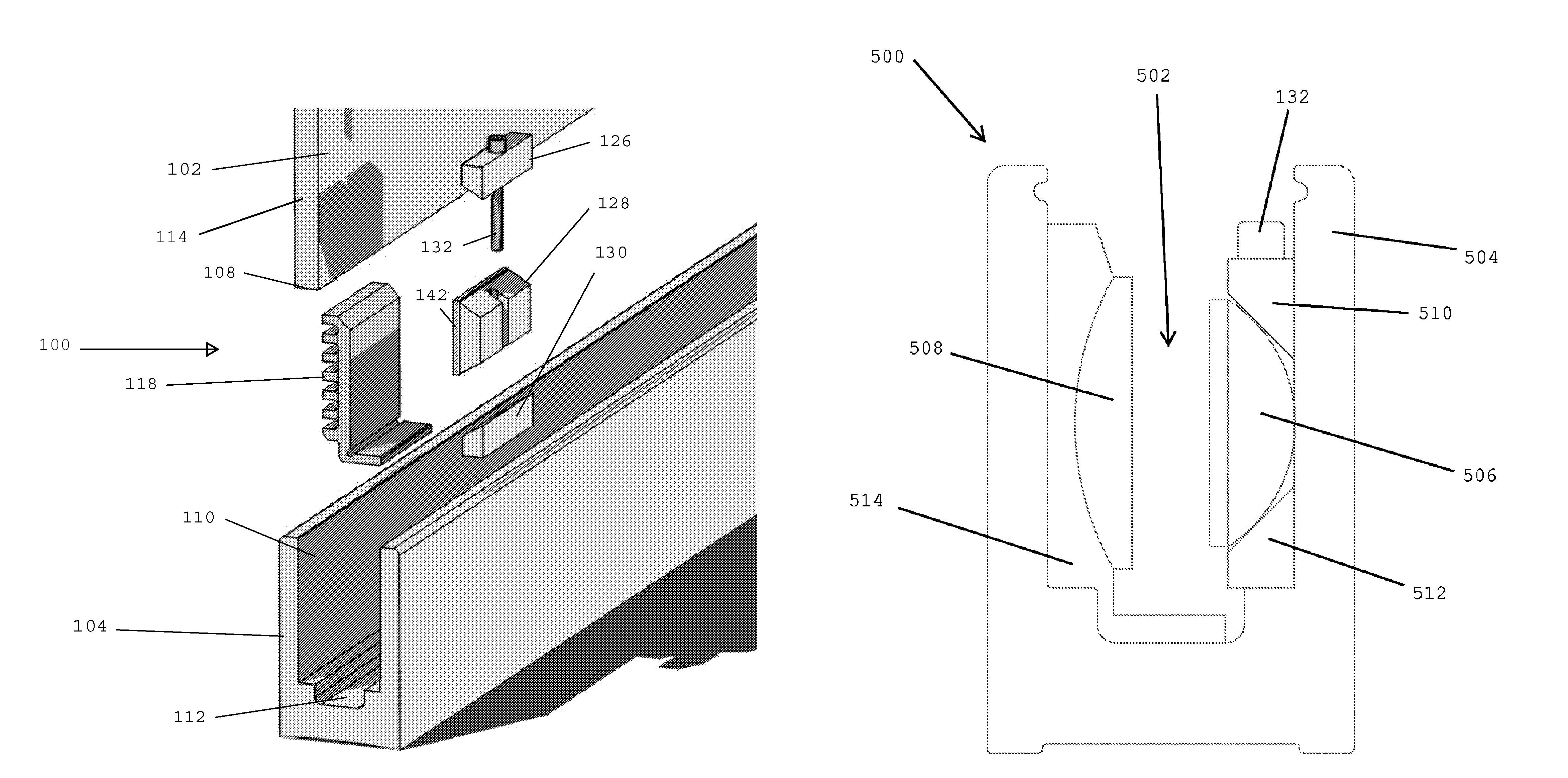
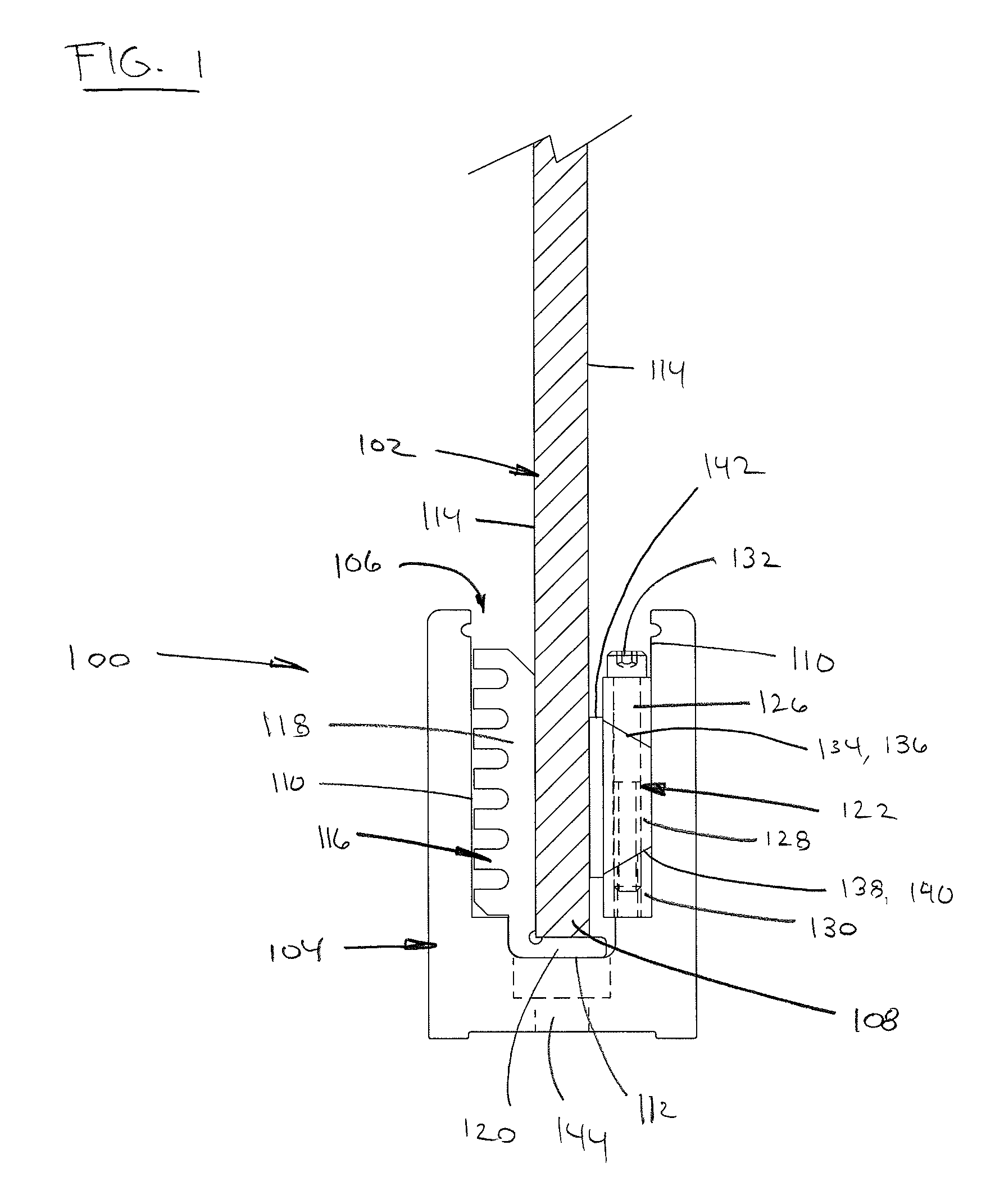
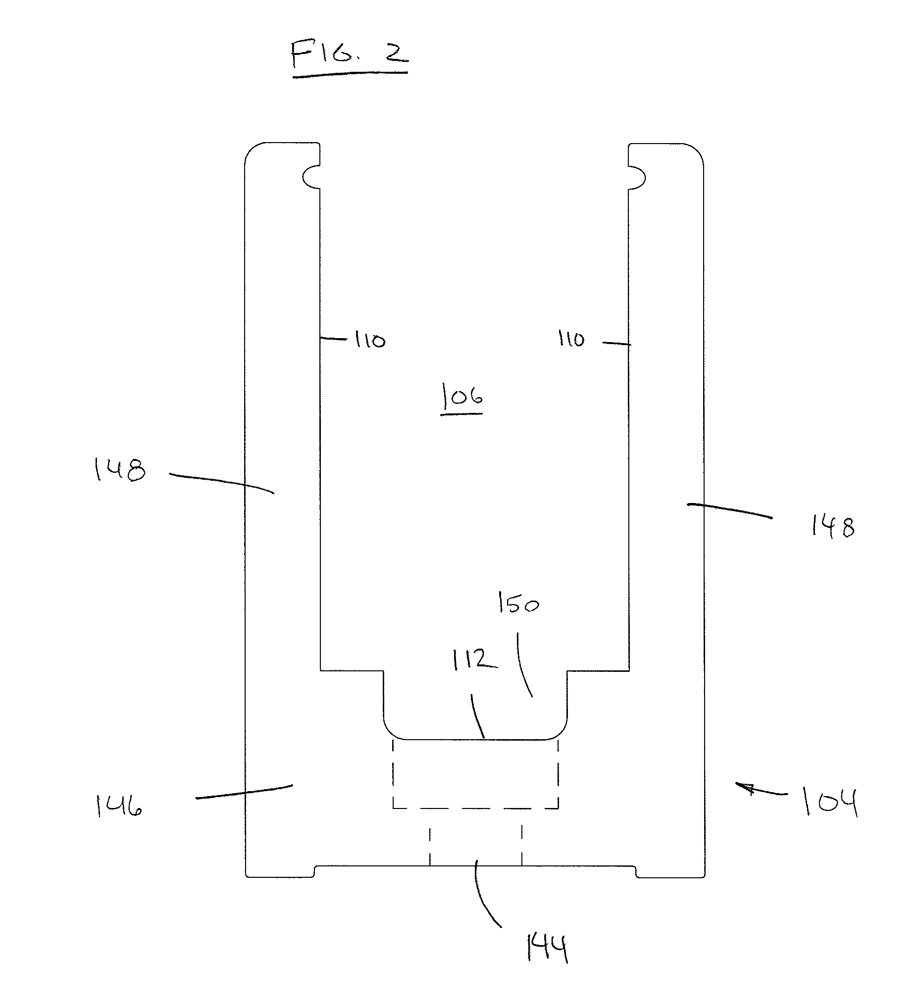
[0046]Referring now to FIGS. 1, and 20 to 23, a system 100 for clamping a partition 102, such as for use in a hand rail, guard rail or other railing system, into a base or shoe 104 is shown. Shoe 104 defines a slot 106 within which a lower edge 108 of partition 102 is received. Slot 106 includes a pair of opposing interior side walls 110 and a lower wall 112. Partition 102 includes a pair of opposing sides 114 adjacent lower edge 108. Within slot 106 between one of the sides 114 and one of the side walls 110 is at least a portion of a first isolator 116. Isolator 116 may include a vertical portion 118 (between side 114 and side wall 110) and a lower portion 120 (between lower edge 108 and lower wall 112).

[0047]Between opposite s...


PUM


Abstract

A system for mounting a partition, the system including a shoe with a slot for receiving an edge of the partition and an isolator that fits within the slot between the partition and a portion of the slot. A clamp assembly fits within the slot opposite the first isolator. The clamp assembly includes upper and lower blocks and a center block. The clamp assembly and the isolator are configured to permit the angling of the partition within the slot to place the partition in a desired position. Surfaces of the blocks are angled with respect to each other so that drawing the upper and lower blocks toward each other will urge the center block in one direction so that the partition is held within the slot.

Description

CROSS-REFERENCE TO RELATED APPLICATION[0001]The present application is a continuation-in-part of U.S. patent application Ser. No. 11 / 832,996, filed on Aug. 2, 2007, now U.S. Pat. No. 7,730,682, issued on Jun. 8, 2010, the disclosure of which is incorporated herein by reference.TECHNICAL FIELD[0002]The present disclosure relates generally to mounting systems and clamp assemblies for mounting partitions.BACKGROUND[0003]It is conventional to use glass or glass-like transparent or semi-transparent partitions as part of a guard rail, hand rail or other railing for a stair or for a walkway. To mount these partitions securely without damaging the glass itself has always been an issue with installation of such partitions. In addition, it may be desirable to provide for removal of the partition without damaging the partition for repair or replacement at some future date.[0004]One conventional system for installing and removably securing partitions in such applications is shown in U.S. Pat. N...

Claims


Application Information

Patent Timeline
Patent Type & Authority Patents(United States)
IPC IPC(8): E04H1/00E04C2/38
CPCE04F11/1851E06B3/5454
Inventor NASH, ALAN C.
Owner R & B WAGNER
Why Eureka
Try Eureka