Probe connector

Inactive Publication Date: 2012-05-22
CHENG UEI PRECISION IND CO LTD
View PDF4 Cites 6 Cited by
  • Summary
  • Abstract
  • Description
  • Claims
  • Application Information

AI Technical Summary

Benefits of technology

[0006]An object of the present invention is to provide a probe connector. The probe connector includes a base shell having a barrel of which a bottom is sealed up by a base board and a top is opened freely. A receiving chamber is defined in the barrel. A top periphery edge of the barrel has two opposite portions protruded upward to respectively form a pair of buckling arms spaced from each other. Two top ends of each pair of buckling arms oppositely protrude sideward to form a pair of buckling barbs. An elastic element has a bottom end thereof inserted downward in the receiving chamber of the barrel and abutting against the base board. A top end of the elastic element stretches upward out of the barrel. A probe pin has a support board of which a middle is punched upward to form a cylindrical touching portion having a top sealed up and a bottom opened freely. A receiving space is accordingly defined in the touching portion. The support board has two opposite portions which are projected beyond two opposite sides of the touching portion define a buckling slot respectively. A pair of resisting arms is provided at two opposite side edges of the support board and inclined towards each other in process of extending downward. The probe pin is movably and removably coupled to the base shell with the top end of the elastic element being inserted in the receiving space and abutting against a top side of the receiving space, by means of each pair of buckling barbs passing through the corresponding bucking slot to make the pair of buckling arms inserted in the buckling slot for guiding the movement of the probe pin. The buckling barbs block over the support board to avoid the probe pin falling off from the base shell, and the resisting arms abut against two opposite outside faces of the barrel.
[0007]As described above, the probe connector of the present invention utilizes the resisting arms to resist against the two opposite outside faces of the barrel, and the buckling arms to be inserted in the buckling slot with the buckling barbs capable of blocking the support board, so as to make the probe pin movably and removably coupled to the base shell. So the probe connector can be easily assembled and disassembled.

Problems solved by technology

So the probe connector has a complicated assembly process, and accordingly, it is hard to disassemble the probe connector on account of the foregoing assembly manner.

Method used


Image

  • Probe connector
  • Probe connector
  • Probe connector

Examples


Embodiment Construction

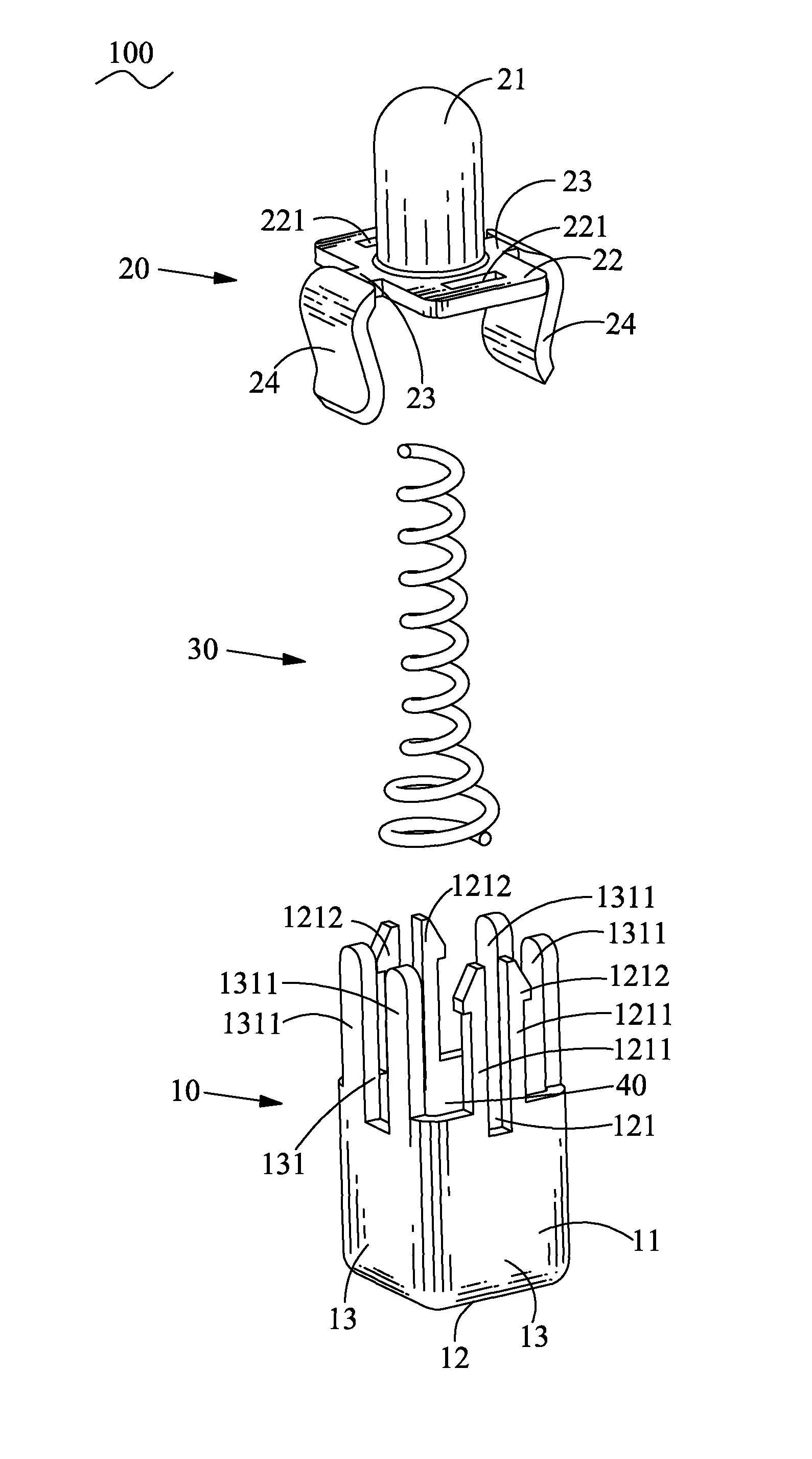
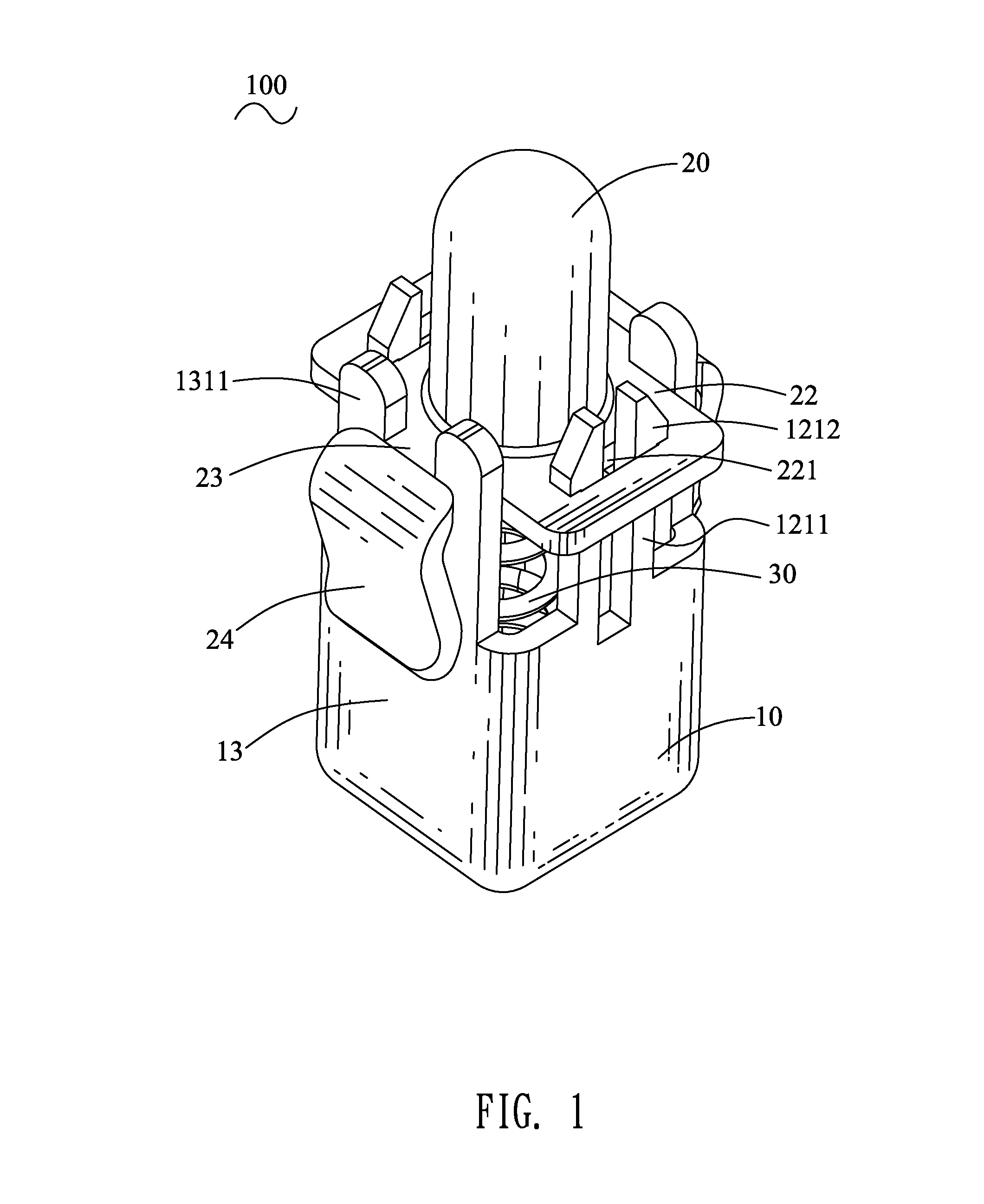
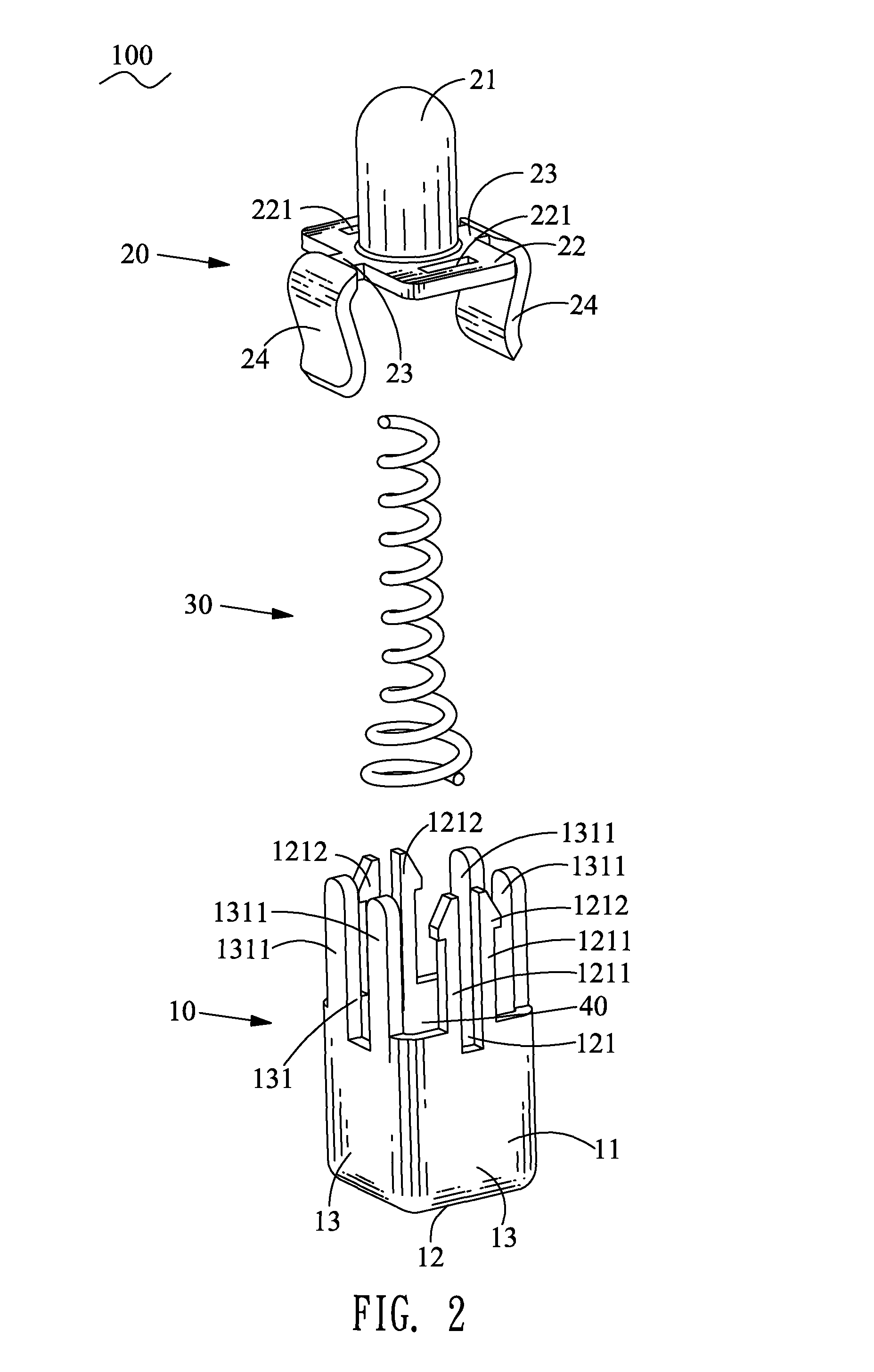
[0012]With reference to FIG. 1, a probe connector 100 according to an embodiment of the present invention includes a base shell 10, a probe pin 20 and an elastic element 30.

[0013]Referring to FIG. 2, the base shell 10 is made of metal material and has a rectangular cylindrical barrel 11 of which a bottom is sealed up by a rectangular base board 12 and a top is opened freely. Four periphery edges of the base board 12 extend upward to form four side boards 13 connected together to define a receiving chamber 40 thereamong. Two opposite ones of the four side boards 13 each has a top edge thereof protruded upward to form a pair of buckling arms 1211 which are spaced from each other to have an elastic space 121 therebetween. The elastic space 121 is further spread downward to the corresponding side board 13. Two top ends of the pair of buckling arms 1211 oppositely protrude sideward to form a pair of buckling barbs 1212. Another two opposite side boards 13 each has a top edge thereof prot...


PUM


Abstract

A probe connector includes a base shell having a barrel of which a top edge has two opposite portions protruded upward to respectively form a pair of buckling arms each having a buckling bard protruded at a top end thereof. A probe pin has a support board of which two opposite ends define a buckling slot respectively and a middle is punched upward to form a touching portion. Two resisting arms are provided at two opposite side edges of the support board and inclined towards each other during extending downward. The probe pin is movably and removably coupled to the base shell with an elastic element assembled in the barrel and the touching portion. The buckling barbs pass through the bucking slots to block over the support board, the buckling arms are inserted in the buckling slots and the resisting arms abut against two opposite outsides of the barrel.

Description

BACKGROUND OF THE INVENTION[0001]1. Field of the Invention[0002]The present invention relates to a connector, and more particularly to a probe connector.[0003]2. The Related Art[0004]A traditional probe connector includes a shell, an elastic element and a probe pin. The probe pin has a cylindrical base portion and a touching portion protruding upward from a middle of a top of the base portion. The shell is made of metal material, and has a hollow barrel looped from a metal plate and having a top end opened freely. In assembly, the elastic element is disposed in the barrel, and the base portion of the probe pin is inserted downward in the barrel, wherein two opposite ends of the elastic element abut against a bottom of the base portion and a bottom side of the barrel. Then an auxiliary jig is used to make a periphery edge of the top end of the barrel shrunk inward so as to block the base portion in the barrel. The touching portion projects out of the top end of the barrel for contact...

Claims


Application Information

Patent Timeline
IPC IPC(8): H01R4/48
CPCH01R13/2421
Inventor LIN, JUI-PIN
Owner CHENG UEI PRECISION IND CO LTD
Why Eureka
Try Eureka