Wheel bearing assembly having a centering device for vehicles

Active Publication Date: 2012-05-03
SAF HOLLAND GMBH
View PDF10 Cites 2 Cited by
  • Summary
  • Abstract
  • Description
  • Claims
  • Application Information

AI Technical Summary

Benefits of technology

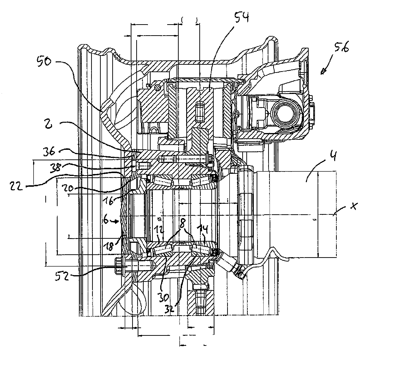
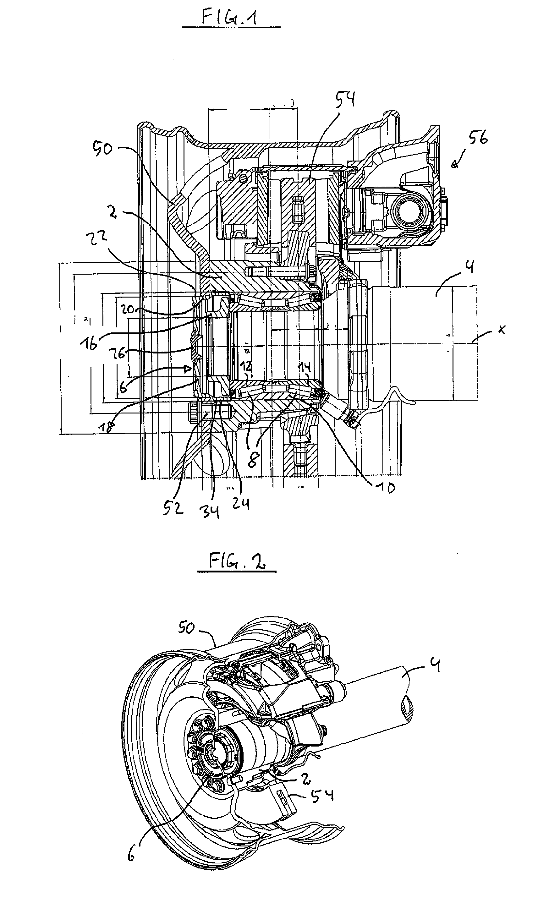
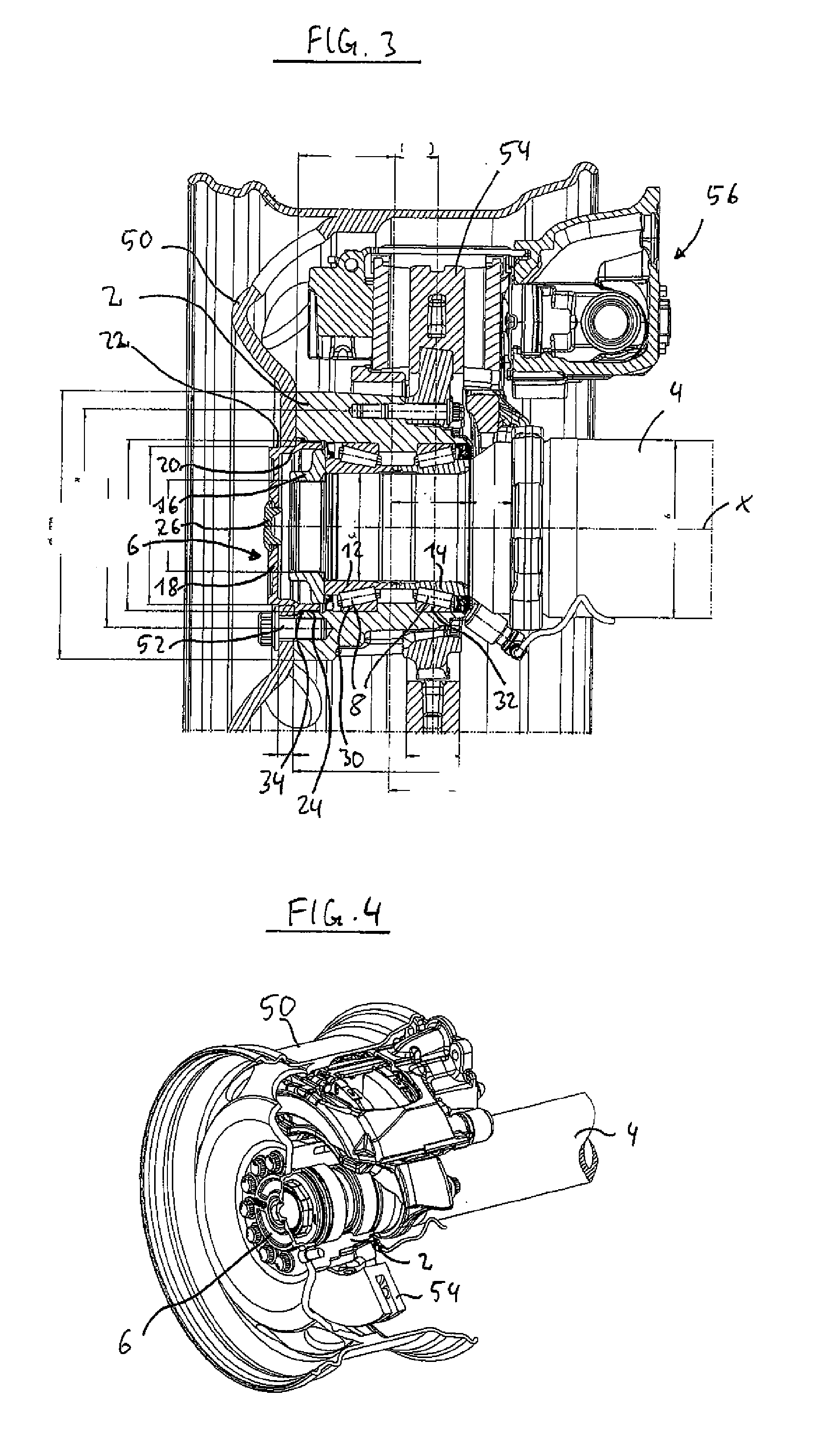
[0011]The centering portion may also be designed rotationally symmetric, wherein the relationship of the diameter of the centering portion to the outer diameter of the bearing assembly amounts to about 0.65 to 0.96, preferably about 0.85 to 0.94, and particularly preferably about 0.92. Due to this optimal relationship it becomes possible to arrange a particularly stable wheel rim without having to change or reduce the size of the axle body, of the wheel hub or of the bearing assembly, which makes the system even more operationally reliable.
[0017]In another embodiment, the centering unit comprises engaging means which are designed to engage with the wheel hub so that the centering unit may be easily assembled and disassembled. The engaging means may be designed for example as external threads on the circumferential portion of the centering unit in the area of the free end thereof, which end is adapted to engage with a corresponding internal thread on the inner circumference of the wheel hub. Additionally or alternatively, there may be provided on the outer circumferential portion a radial groove or a radial recess which comes to engage with a radial projection or a radial groove, respectively, arranged on the inner circumference of the wheel hub, in order to fix the centering unit on the wheel hub. Additionally or alternatively, there may also be provided screws / bolts, studs, rivets or similar elements which preferably extend through openings in the flange portion of the centering unit and which are being fastened to the wheel hub. Advantageously, the engaging means also make it possible to prevent damage to the components of the wheel hub unit due to thermal influences or a partial heating, respectively, as is the case in the solutions known from the prior art, where the centering unit is firmly bonded and unreleasably fastened to the wheel hub (e.g. by means of welding or brazing / soldering).

Problems solved by technology

A problem of such wheel hub or wheel bearing assemblies, however, is that due to the centering projection in the wheel hub the minimum diameter of the central opening of the wheel rim is limited.
However, a problem of such systems is that the wheel bearing unit is subject to enormous thermal stresses since the pot of the pot-shaped brake disc shields the wheel bearing unit from cooling from the outside and, in addition, heat may be introduced directly into the wheel bearing unit during the braking process.

Method used


Image

  • Wheel bearing assembly having a centering device for vehicles
  • Wheel bearing assembly having a centering device for vehicles
  • Wheel bearing assembly having a centering device for vehicles

Examples


Embodiment Construction

[0026]For purposes of description herein, the terms “upper,”“lower,”“right,”“left,”“rear,”“front,”“vertical,”“horizontal,” and derivatives thereof shall relate to the invention as oriented in FIG. 1. However, it is to be understood that the invention may assume various alternative orientations, except where expressly specified to the contrary. It is also to be understood that the specific devices and processes illustrated in the attached drawings, and described in the following specification are simply exemplary embodiments of the inventive concepts defined in the appended claims. Hence, specific dimensions and other characteristics relating to the embodiments disclosed herein are not to be considered as limiting, unless the claims expressly state otherwise.

[0027]FIGS. 1 and 2 show a first exemplary embodiment of a wheel hub or wheel bearing assembly according to the invention, comprising a centering device for wheels to be attached thereto. The wheel hub or wheel bearing assembly c...


PUM


Abstract

A wheel bearing assembly with a centering device that includes a wheel hub arranged rotatably on an axle body about an axis of rotation. The assembly further includes a centering unit fixed to the wheel hub, wherein the centering unit has a centering portion, and wherein the distance of the centering portion to the axis of rotation is smaller than the distance of the outer periphery of the wheel hub to the axis of rotation.

Description

BACKGROUND OF THE INVENTION[0001]The present invention relates to a wheel hub or wheel bearing assembly with a centering device for vehicles, such as commercial vehicles or farm vehicles.[0002]Wheel hub or wheel bearing assemblies of the type in question are known from the prior art. For example, DE 100 49 615 A1 discloses a wheel hub or wheel bearing assembly having a wheel hub which is supported rotatably on an axle body. In order to center the wheel, the wheel hub comprises a recess. A problem of such wheel hub or wheel bearing assemblies, however, is that due to the centering projection in the wheel hub the minimum diameter of the central opening of the wheel rim is limited. In order to overcome this problem, there exist wheel hub or wheel bearing assemblies with a centering device which is smaller than the inner diameter of the wheel hub, by arranging a pot-shaped brake disc upstream of the bearing assembly, which brake disc has a corresponding centering seat of a smaller diame...

Claims


Application Information

Patent Timeline
IPC IPC(8): B60B27/02
CPCB60B7/066B60B27/001
Inventor DREWES, OLAF
Owner SAF HOLLAND GMBH
Why Eureka
Try Eureka