Center pivot irrigation system position sensing system

a technology of position sensing and irrigation system, which is applied in the direction of watering devices, navigation instruments, instruments, etc., can solve the problems of unnecessarily complex approach, unfavorable remote monitoring of the angular orientation of the rotatable arm, and inability to remotely control the operation of the various aspects

Active Publication Date: 2012-05-22
AGSENSE
View PDF18 Cites 14 Cited by
  • Summary
  • Abstract
  • Description
  • Claims
  • Application Information

AI Technical Summary

Benefits of technology

[0018]A significant advantage of the present invention is the simplicity of associating actions or functions of the irrigation system with the coordinates of the location of a tower unit positioned on the irrigations system's rotatable arm when the action or functions is to occur, so that the system is able to compare the coordinates associated with the action or function with the coordinates of the current location, and when a substantial match occurs, the action or function is initiated. The present invention does not require the calculation of angle or azimuths using multiple coordinates to determine the current position of the rotatable arm.

Problems solved by technology

However, the systems tend to be relatively complex, particularly since the known GPS-based systems still rely upon the technique of determining the angular orientation of the rotatable arm for controlling the center pivot irrigation system.
This approach is believed to be unnecessarily complex for this purpose, and does not readily lend itself to remotely monitoring of the angular orientation of the rotatable arm, or to remotely controlling the operation of the various aspects of the center pivot irrigation system.
Further, most if not all known systems utilize monitoring and programming operations that are performed in the field, or at least must be changed in the field, and this factor makes the operation of the system more difficult, or at least inconvenient, for the operator of the system, especially for operators that are responsible for monitoring and controlling multiple center pivot irrigation systems.

Method used


Image

  • Center pivot irrigation system position sensing system
  • Center pivot irrigation system position sensing system
  • Center pivot irrigation system position sensing system

Examples


Embodiment Construction

[0029]With reference now to the drawings, and in particular to FIGS. 1 through 8 thereof, a new irrigation arm position sensing system embodying the principles and concepts of the present invention and generally designated by the reference numeral 10 will be described.

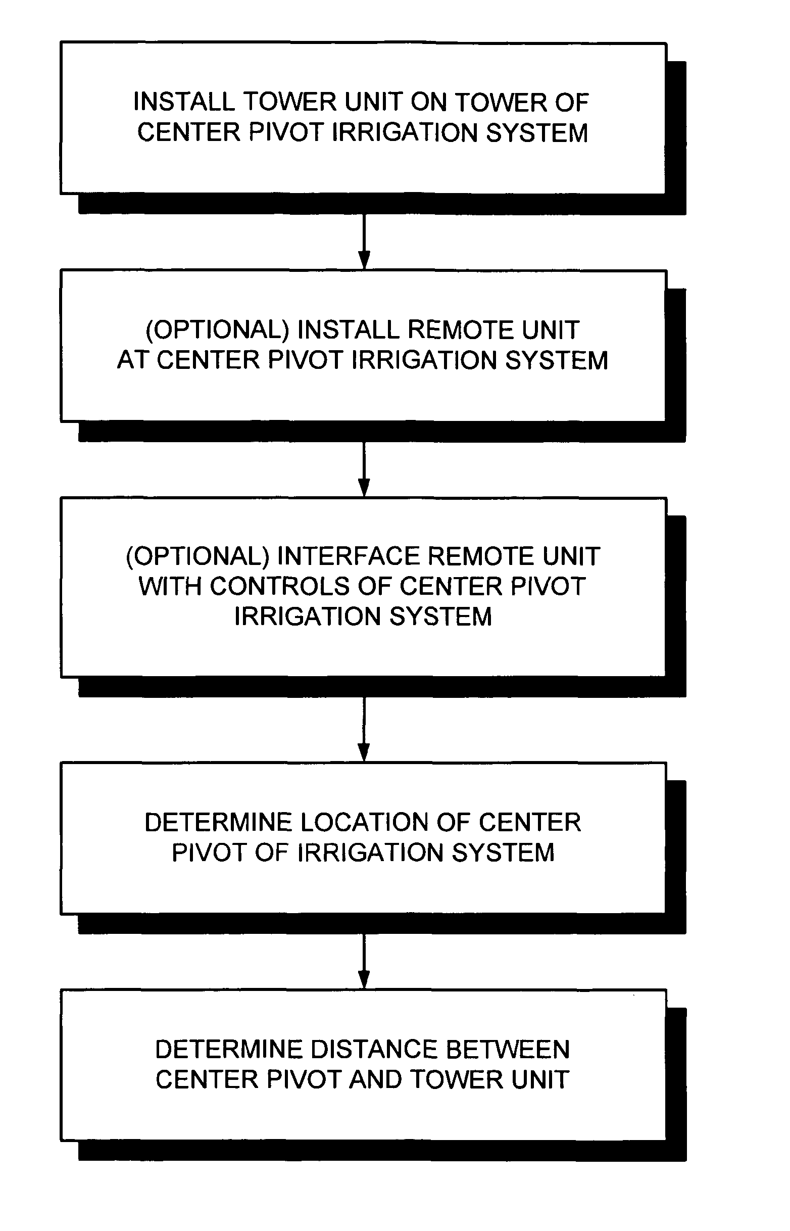
[0030]In general, the irrigation arm position sensing system 10 of the invention employs a technique of determining a present location of an element of the system 10 that is mounted on the center pivot irrigation system 1, and comparing the present location of the element to a number of locations stored on the system 10, and then executes a function or action of the irrigation system 1 that is associated with that location during the operation of the irrigation system. The need to calculate the angular orientation of the center pivot irrigation system 1 is thus rendered superfluous and unnecessary for control of the irrigation system 1.

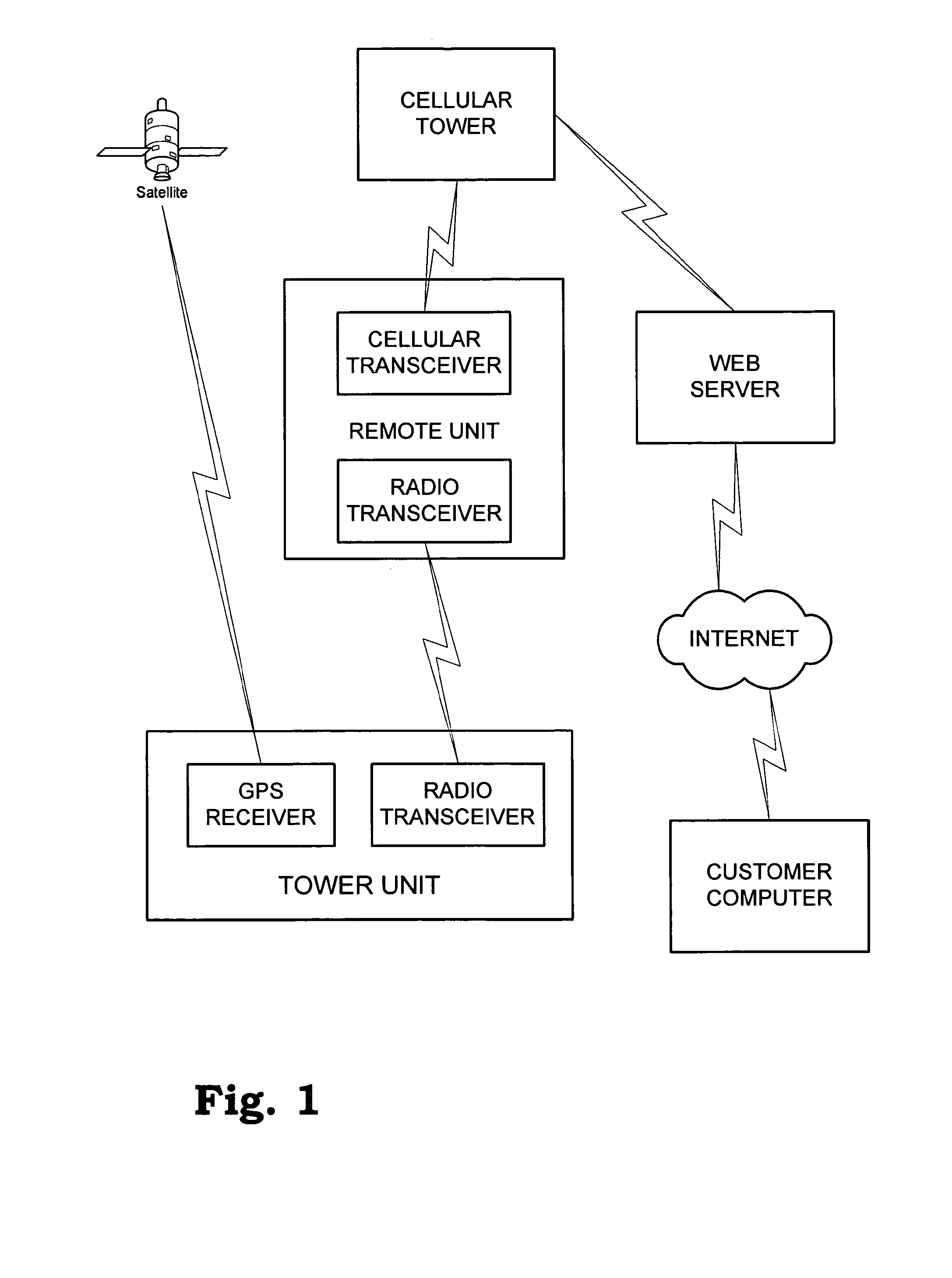
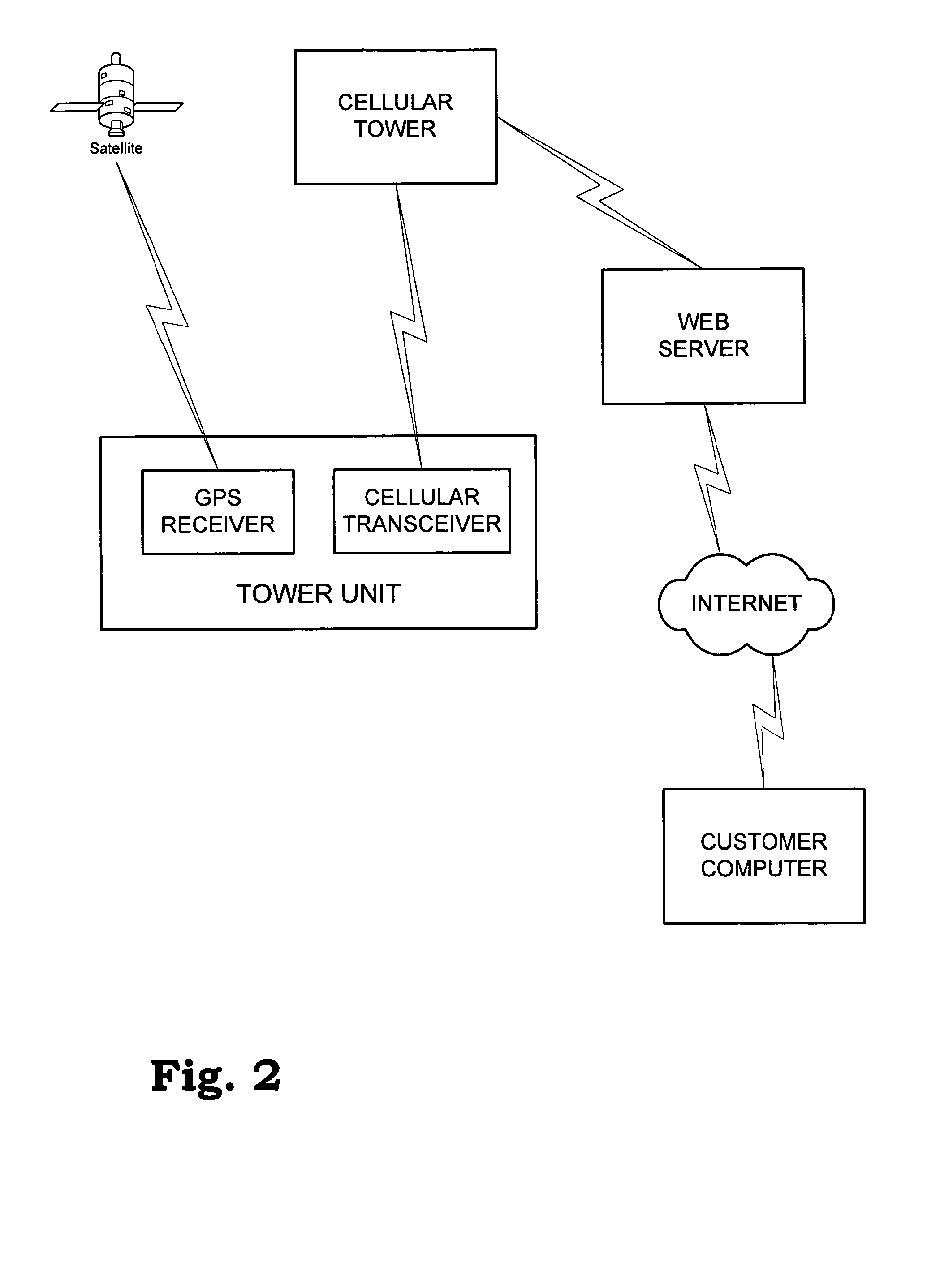
[0031]In greater detail, as best illustrated in FIGS. 1 and 2 of the drawings, one a...


PUM


Abstract

A system and method for determining a position of a center pivot irrigation system includes positioning a tower unit on the rotatable arm of the irrigation system, determining a distance between the arm's rotation center and the tower unit, calculating coordinates of the tower unit along a path of the tower unit as the arm rotates, and associating an action of the irrigation system with coordinates of the tower unit location that correspond to the position of the arm where the action is to occur. Optionally, the action of the irrigation system and the coordinates of the location of the tower unit are downloaded to a remote unit located adjacent to the irrigation system. Optionally, current location coordinates of the tower unit are determined using a GPS receiver at the tower unit. Optionally, the current location coordinates are transmitted from the tower unit to the remote unit. Optionally, the current location coordinates are compared to the coordinates of the location of the action. If a substantial match of the current location coordinates with the location coordinates associated with an action is detected, the action may be initiated by the remote unit through controls of the irrigation system.

Description

REFERENCE TO RELATED APPLICATION[0001]This application is a continuation of U.S. patent application Ser. No. 11 / 649,555 filed Jan. 4, 2007, which was issued on May 31, 2011 as U.S. Pat. No. 7,953,550, which is hereby incorporated by reference in its entirety.BACKGROUND OF THE INVENTION[0002]1. Field of the Invention[0003]The present invention relates to apparatus for sensing the position of a center pivot irrigation system in a field, and more particularly pertains to a new system for determining the position of the rotatable arm of a center pivot irrigation system using data from a Global Positioning Satellite (GPS), which may be used in controlling various aspects of the function of the center pivot irrigation system using a network-based system interface.[0004]2. Description of the Prior Art[0005]Irrigation systems have been employed for years to distribute water to areas of land on which a crop is growing. One type of irrigation system, the so-called “center pivot” system, emplo...

Claims


Application Information

Patent Timeline
Patent Type & Authority Patents(United States)
IPC IPC(8): B05B12/00
CPCA01G25/092
Inventor WIETING, MEL
Owner AGSENSE
Why Eureka
Try Eureka