
Method and apparatus for strobe-based source-synchronous capture using a first-in-first-out unit

a strobe-based source and synchronous capture technology, applied in the field of methods and apparatus for strobe-based sourcesynchronous capture using a first, can solve the problems of complexity associated with the hardware needed to support dynamic delay calibration, difficulty in completing a synchronous transfer with a single central board clock or even a single clock forwarded with a large number, and additional complexity in the controller logic to keep, so as to avoid timing marginality

Active Publication Date: 2012-05-22
ALTERA CORP
View PDF4 Cites 3 Cited by
  • Summary
  • Abstract
  • Description
  • Claims
  • Application Information

AI Technical Summary

Benefits of technology

The present invention describes a way to synchronize data from different clock domains using an asynchronous FIFO unit. This unit allows for the re-synchronization of data without the need for specialized hardware or complicated timing processes. The FIFO unit can handle transfers from multiple strobe domains to a single clock domain asynchronously, without any timing interactions. The technical effect of this invention is improved data synchronization and reduced timing uncertainty in data transfer.

Problems solved by technology

Board skews and delay variation make it challenging to complete a synchronous transfer with a single central board clock or even a single clock forwarded with a large number of data bits.
One issue with this approach is that data synchronized to various different clocks or strobes must often be synchronized to a single clock in the receiving device to facilitate data processing on all the data received.
The disadvantage of this approach is the complexity associated with the hardware needed to support dynamic delay calibration to adjust delays for process / voltage / temperature variations.
There can be additional complexity in the controller logic to keep the data capture reliable and ensure all the data is aligned.
A disadvantage with this approach is it can be difficult if not impossible to determine a single clock phase within the receiving device that will suit all the clock / strobe domains at high speeds.
Another challenge with source-synchronous transfer relates to the fact that strobe signals may not be free-running.
This complicates some synchronization approaches.

Method used


Image

  • Method and apparatus for strobe-based source-synchronous capture using a first-in-first-out unit
  • Method and apparatus for strobe-based source-synchronous capture using a first-in-first-out unit
  • Method and apparatus for strobe-based source-synchronous capture using a first-in-first-out unit

Examples


Embodiment Construction

[0016]In the following description, for purposes of explanation, specific nomenclature is set forth to provide a thorough understanding of embodiments of the present invention. It will be apparent to one skilled in the art that specific details in the description may not be required to practice the embodiments of the present invention. In other instances, well-known circuits, devices, and components are shown in block diagram form to avoid obscuring embodiments of the present invention unnecessarily.

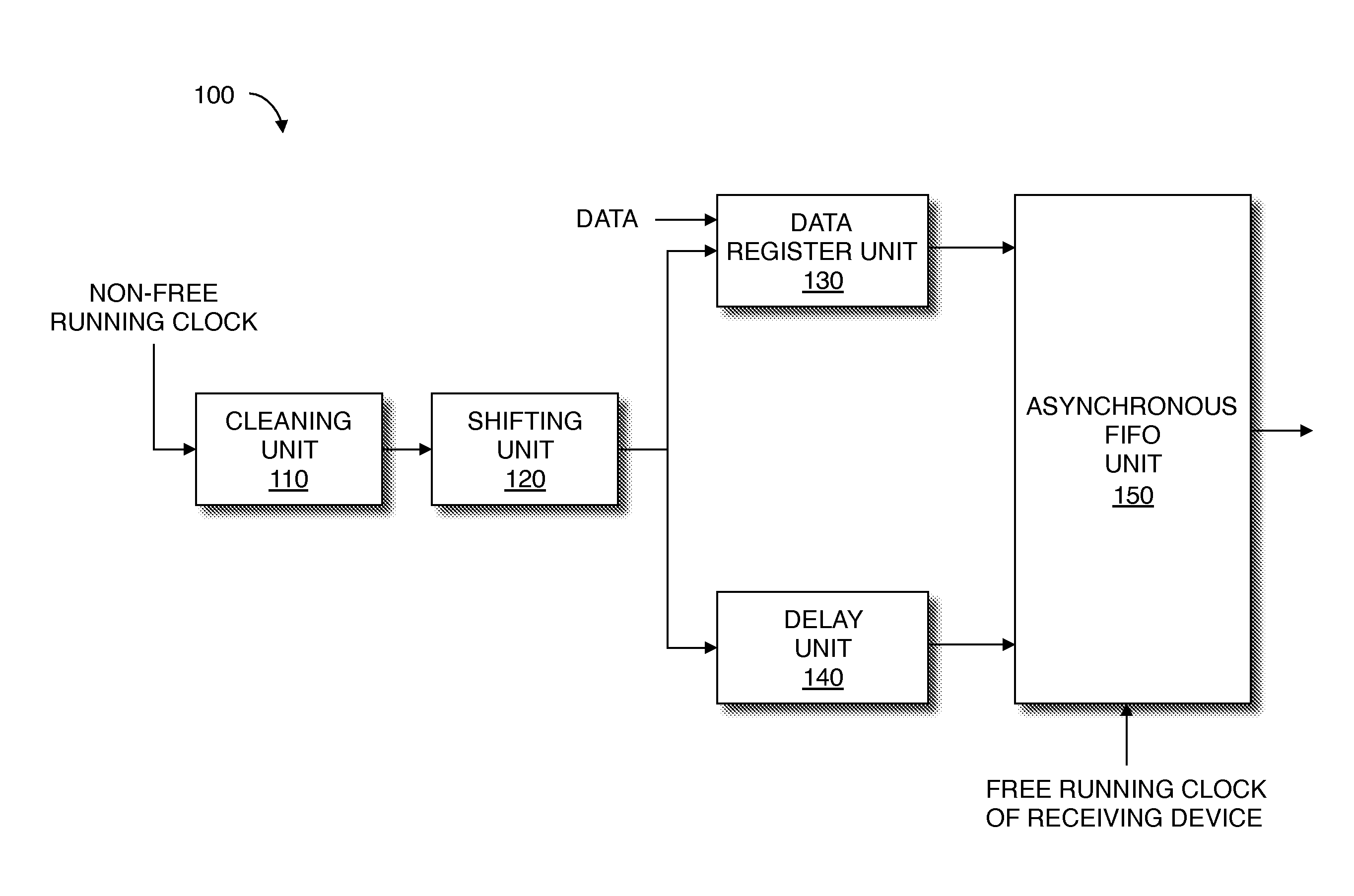
[0017]FIG. 1 is a block diagram of a source synchronous capture unit 100 according to an exemplary embodiment of the invention. The source synchronous capture unit 100 may be used at a receiving device to capture source synchronous data from a transmitting device and to synchronize the data to a receiving device clock. The source synchronous capture unit 100 can support source-synchronous communication standards, such as DDR, that do not send a free-running clock along with the data. A n...


PUM


Abstract

A source-synchronous capture unit includes a data register unit to register data synchronized to a strobe or non-free running clock. The source synchronous capture unit also includes an asynchronous first-in-first-out (FIFO) unit to store the data from the data register unit in response to the strobe or non-free running clock and to output the data stored, in response to another clock.

Description

RELATED APPLICATION[0001]This patent application is a continuation of and claims priority and benefit to U.S. application Ser. No. 11 / 712,143, now U.S. Pat. No. 8,015,382 filed on Feb. 28, 2007 entitled “Method and Apparatus for Strobe-Based Source-Synchronous Capture Using a First-In-First-Out Unit”, the disclosure of which is incorporated herein by reference.FIELD OF THE INVENTION[0002]Embodiments of the present invention relate to hardware for supporting source synchronous standards such as that used with double-data-rate (DDR) memory. More specifically, embodiments of the present invention relate to a method and apparatus for strobe-based source-synchronous capture using a first-in-first-out (FIFO) buffer.BACKGROUND OF THE INVENTION[0003]Source synchronous communication standards are important to enable high-speed data transfer between devices. Board skews and delay variation make it challenging to complete a synchronous transfer with a single central board clock or even a singl...

Claims


Application Information

Patent Timeline
Patent Type & Authority Patents(United States)
IPC IPC(8): G06F13/00
CPCG06F13/00G06F5/06G11C7/22
Inventor FUNG, RYAN
Owner ALTERA CORP
Features
  • Generate Ideas
  • Intellectual Property
  • Life Sciences
  • Materials
  • Tech Scout
  • Unparalleled Data Quality
  • Higher Quality Content
  • 60% Fewer Hallucinations
Learn More