Ladders, ladder components and related methods

a technology of ladders and components, applied in the direction of building scaffolds, manufacturing tools, rod connections, etc., can solve the problems of difficulty in temporary storage of ladder tools or other items, and difficulty in adjusting the height of ladders

Active Publication Date: 2012-05-29
LITTLE GIANT LADDER SYST LLC
View PDF59 Cites 103 Cited by
  • Summary
  • Abstract
  • Description
  • Claims
  • Application Information

AI Technical Summary

Problems solved by technology

Sometimes the use of a ladder can be an awkward experience, even for those who use ladders on a regular basis, when certain tasks are to be performed while standing on a ladder.
For example, it can be easy to lose one's balance on a ladder while working on an overhead project (e.g., painting a ceiling, changing a light bulb, etc.) Moreover, when one needs to utilize tools or access other resources (e.g., hardware, paint, etc.) while working on a ladder, temporary storage of such tools or other items is often problematic.
Often, the user of a ladder may have to make many trips up and down the ladder to exchange tools or other equipment during the performance of a particular job making the use of the ladder less efficient than it could be.
Additionally, operation of some ladders is not always simple, efficient or safe.
For example, in collapsing the spreaders of an A-frame type stepladder can result in the pinching of ones fingers or hands.
Similarly, when ladders are adjustable in height or adjustable from one configuration to another, the associated actuation mechanism used to effect the adjustments may result in pinched hands or fingers or, in many cases, just difficulty in efficiently effecting the actuation at all.
Such an action can be awkward and difficult for some people to perform.
In many cases, such as when smaller users are trying to adjust the height of the ladder, significant effort may be required.

Method used


Image

  • Ladders, ladder components and related methods
  • Ladders, ladder components and related methods
  • Ladders, ladder components and related methods

Examples


Embodiment Construction

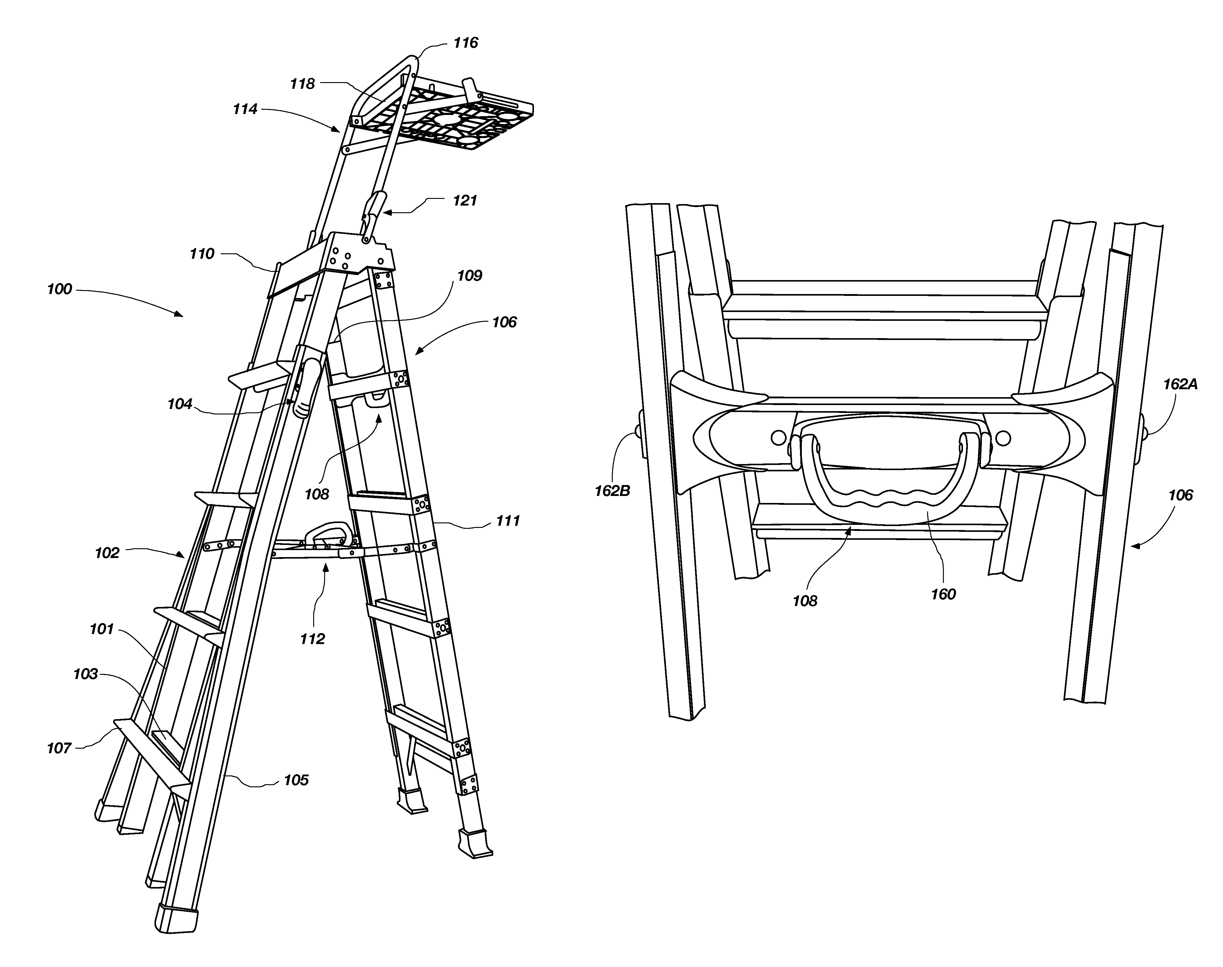
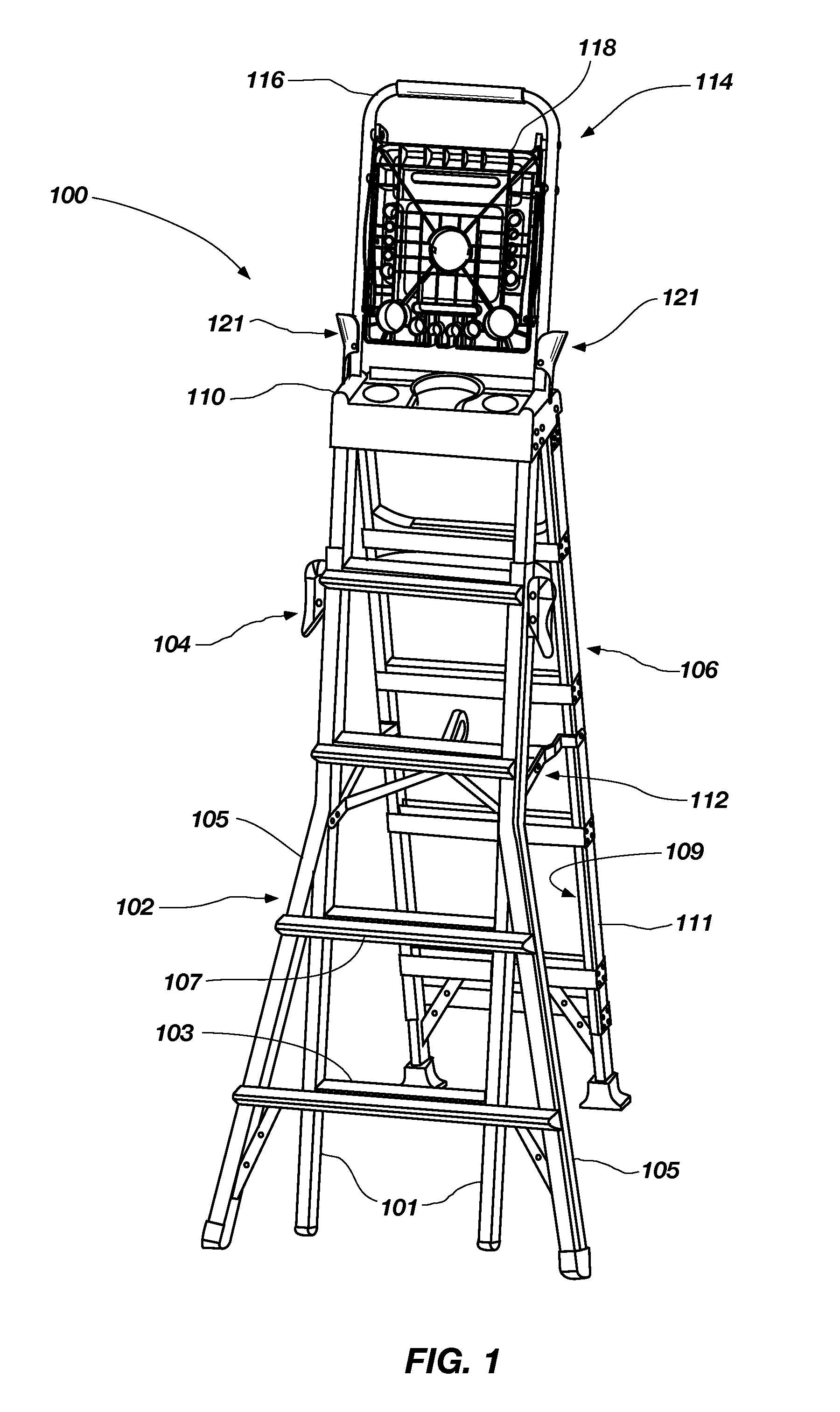
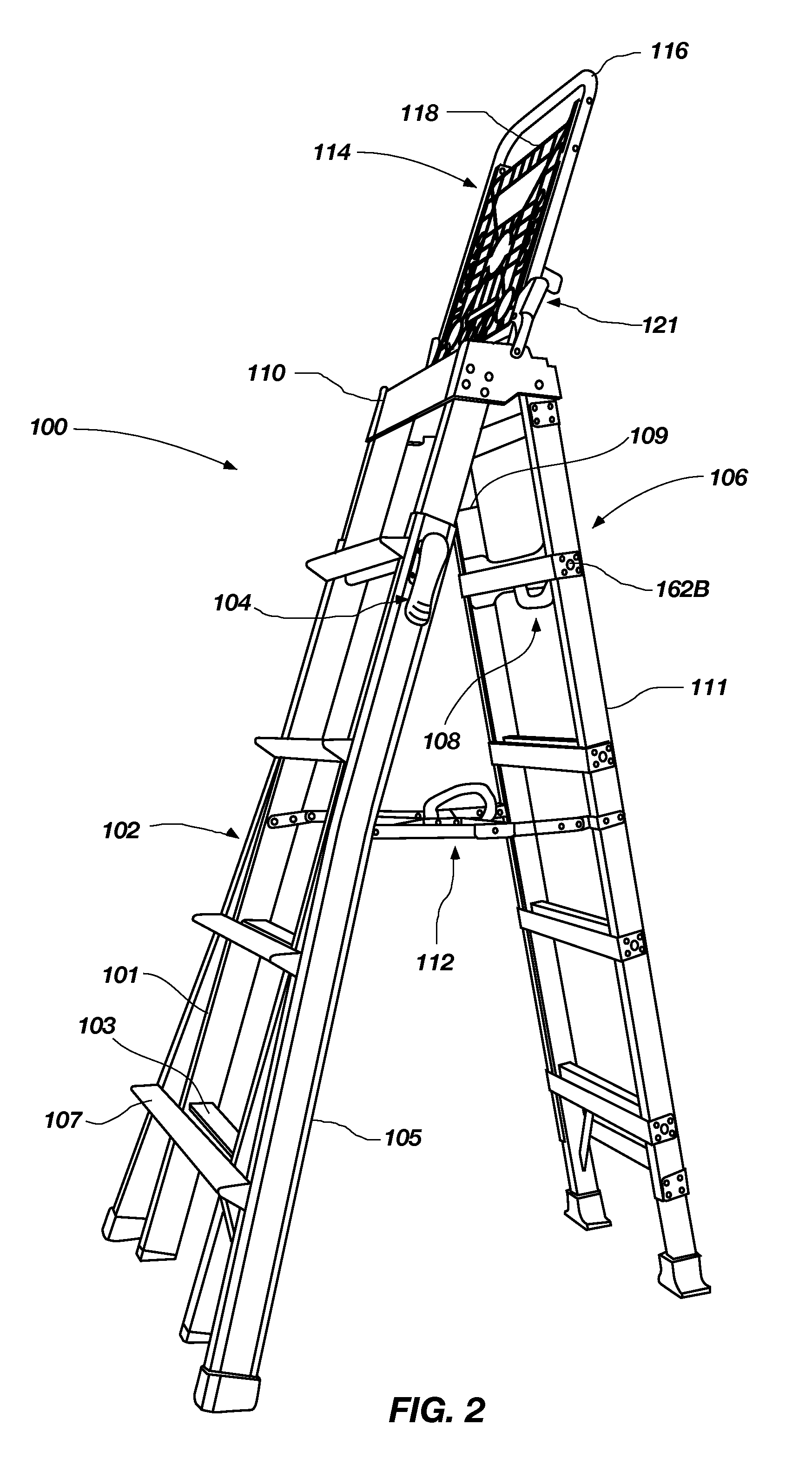
[0037]Referring to FIGS. 1 through 4, a ladder 100 is shown in accordance with an embodiment of the present invention. The ladder 100 is shown as a stepladder and includes a first assembly 102 including inner rails 101 having a plurality of rungs 103 extending between, and coupled to, the inner rails 101. The first assembly 102 further includes outer rails 105 connected by a plurality of rungs 107. The inner and outer rails 101 and 105 are slidably connected to each other such that they may be extended or retracted to exhibit different heights. One such assembly is described in U.S. Pat. No. 4,210,224 to Kummerlin, the disclosure of which is incorporated by reference herein in its entirety. The first assembly 102 further includes a locking mechanism 104 coupled with the outer rails 105 and configured to engage or release the inner rails 101 from the outer rails 105 so that they may be selectively displaced relative to one another and effect different ladder heights. The locking mech...


PUM

PropertyMeasurementUnit
angleaaaaaaaaaa
lengthaaaaaaaaaa
shapesaaaaaaaaaa

Abstract

Ladders, ladder components and related methods are provided. In some embodiments, adjustable stepladders are provided which include locking mechanisms that enable height adjustment of the ladder through application of a force towards the rails of the ladder. In other embodiments, spreader mechanisms are provided with cross bracing located and configured to provide additional stability to the ladder while also incorporating a handle that enables efficient collapsing of the ladder while reducing the potential of pinching ones hands or fingers. In another embodiment, a device is provided for selective coupling with the ladder that includes a support or safety rail and an adjustable tray. The device may be coupled with the ladder in a number of different positions including a stowed position. In another embodiment, a hinge assembly is provided having a magnetic component configured to be magnetically coupled with and temporarily store an object on the ladder.

Description

CROSS-REFERENCE TO RELATED APPLICATIONS[0001]The present application claims the benefit of U.S. Provisional Application No. 61 / 068,656 entitled LADDERS, LADDER COMPONENTS AND RELATED METHODS, filed Mar. 7, 2008, the disclosure of which is incorporated by reference herein in its entirety.TECHNICAL FIELD[0002]The present invention relates generally to ladders, ladder systems, ladder components and related methods and, more specifically, to adjustable rail configurations, rail structures, locking mechanisms, trays and platform configurations, hinge configurations and related methods of manufacturing and operating the same.BACKGROUND[0003]Ladders are conventionally used to provide a user thereof with improved access to locations that might otherwise be inaccessible. Ladders come in many shapes and sizes, such as straight ladders, straight extension ladders, stepladders, and combination step and extension ladders. So-called combination ladders incorporate, in a single ladder, many of the...

Claims


Application Information

Patent Timeline
Patent Type & Authority Patents(United States)
IPC IPC(8): E06C1/00E06C5/32
CPCE06C1/18E06C7/14E06C1/22E06C7/50Y10T16/522Y10T29/49826E06C7/04F16B7/105E06C7/16
Inventor MOSS, N. RYANCRAWFORD, RYANEMMEL, KEITH
Owner LITTLE GIANT LADDER SYST LLC
Why Eureka
Try Eureka