Screen device

Active Publication Date: 2012-06-05
METACO INC
View PDF39 Cites 8 Cited by
  • Summary
  • Abstract
  • Description
  • Claims
  • Application Information

AI Technical Summary

Benefits of technology

[0015]According to the first aspect of the invention, since the weight moving in the height direction interlocking with development and reception of the slide guide frames brakes reception of the slide guide frames owing to an increase in potential energy, it is possible to decrease the slide bar in sliding speed at the time of closing of the screen device. Accordingly, the screen device is improved in safety.
[0016]Also, since the weight promotes development of the slide guide frames owing to a decrease in potential energy, it is possible to decrease an operating force applied to the slide bar at the time of closing of the screen device, so that an operation feeling is nimble.
[0017]According to the second aspect of the invention, since the weight is received in the slide bar, an outward appearance can be maintained favorable as heretofore and

Problems solved by technology

Also, since the slide bar 2 is pulled toward the stationary frame 1 at all times, the slide bar 2 automatically slides at the t

Method used


Image

  • Screen device
  • Screen device
  • Screen device

Examples


Embodiment Construction

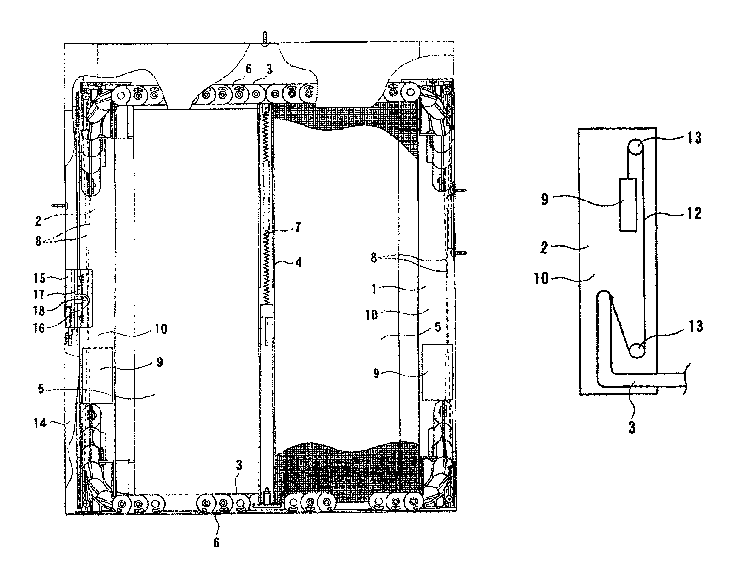
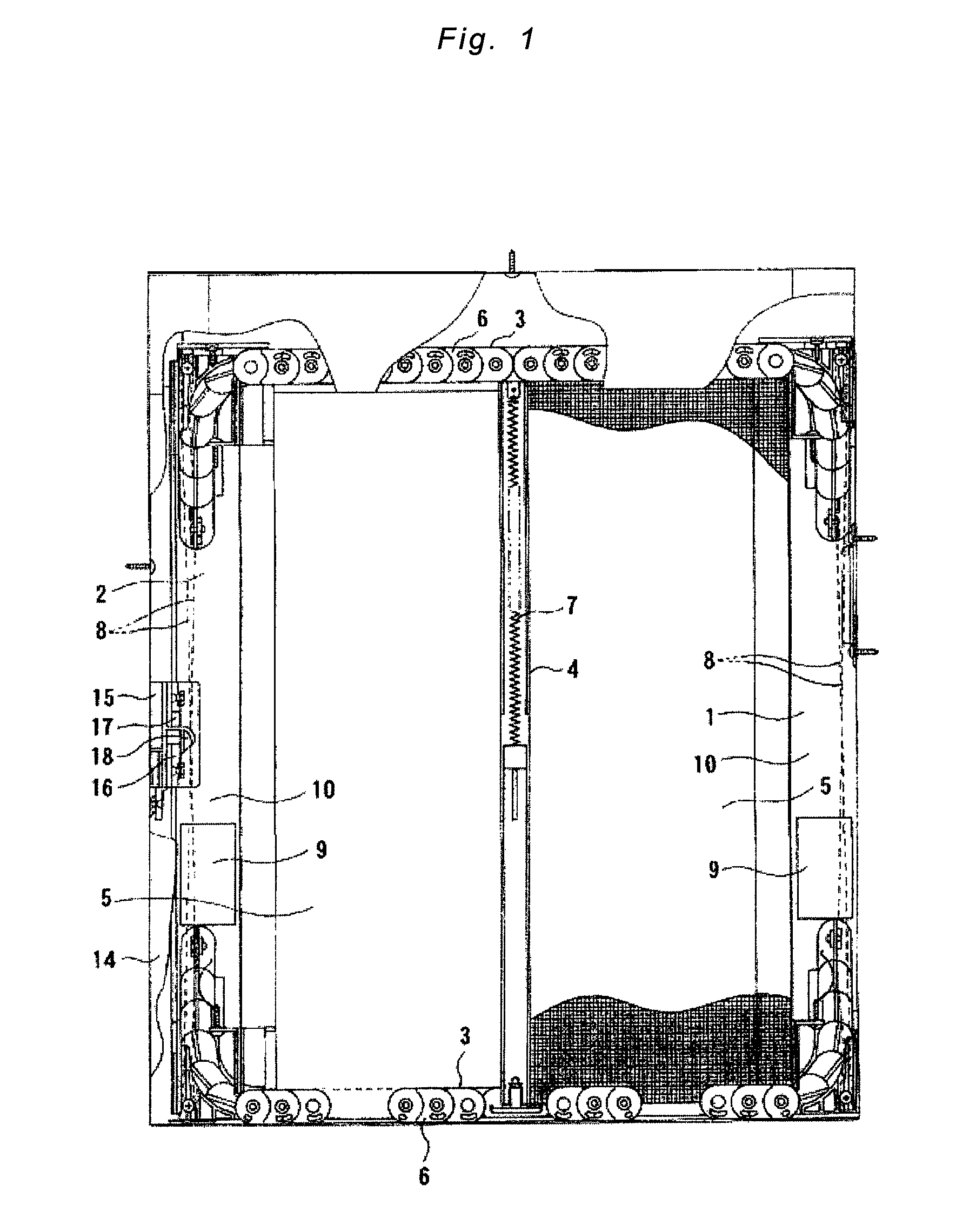
[0024]FIG. 1 is a front view showing an embodiment of a screen device, according to the invention, with a part thereof cut out.

[0025]With the screen device shown in FIG. 1, a slide bar 2 is provided to be slidable horizontally relative to a stationary frame 1. A pair of slide guide frames 3 are provided above and below, the respective slide guide frames 3 being formed by connection of a plurality of rigid units 6. The slide guide frames 3 can bend in one direction but do not bend in the other direction to hold straightness. Both ends of the slide guide frames 3 are free to enable development from and reception in both the slide bar 2 and the stationary frame 1. That is, as the slide bar 2 slides, the slide guide frames 3 are developed from the slide bar 2 and the stationary frame 1 and received in the slide bar 2 and the stationary frame 1. In a state of being developed, the slide guide frames 3, respectively, define upper and lower frames of the screen device.

[0026]A rotatable roll...


PUM


Abstract

A weight moving in a height direction interlocking with development and reception of a slide guide frame is provided, and the weight brakes reception of the slide guide frame owing to an increase in potential energy and promotes development of the slide guide frame owing to a decrease in potential energy, whereby an operating force is decreased, a feeling of operating a slide bar is made light, and the slide bar is decreased in sliding speed at the time of closing to achieve an improvement in safety.

Description

BACKGROUND OF THE INVENTION[0001]I. Technical Field[0002]The present invention relates to a screen device that can be used as curtain, blind, screen, partitioning, etc.[0003]II. Description of the Related Art[0004]The applicant of the present application has proposed a versatile screen device being ready, smooth, and stable in opening and closing operations (JP-A-2005-351046).[0005]As shown in FIG. 5, a slide bar 2 being slidable relative to a stationary frame 1 is provided on a screen device. Also, a pair of slide guide frames 3 are provided, the slide guide frames 3 being developed from and received in the slide bar 2 as the slide bar 2 slides. A rotatable roller pipe 4 is arranged between the pair of slide guide frames 3. The rotatable roller pipe 4 is also slidable along the slide guide frames 3. One end of each of two screens 5 are fixed to the roller pipe 4. In the case where the roller pipe 4 is single, as shown in FIG. 5, one end of each of the single screens 5 is fixed to t...

Claims


Application Information

Patent Timeline
IPC IPC(8): E06B9/08A47H1/00A47G5/02E06B9/56
CPCE06B9/54E06B2009/543
Inventor OKACHI, YASUBUMINISHIOKA, YUICHIRO
Owner METACO INC
Why Eureka
Try Eureka