Airfoil shape for a compressor blade

a compressor blade and airfoil technology, applied in the field of compressor blade airfoil profiles, can solve the problems of not being robust enough or permanent enough to provide design goals and desired requirements, and achieve the effect of reducing the number of airfoils

Active Publication Date: 2012-06-05
GE INFRASTRUCTURE TECH INT LLC
View PDF4 Cites 36 Cited by
  • Summary
  • Abstract
  • Description
  • Claims
  • Application Information

AI Technical Summary

Problems solved by technology

Past efforts to meet design goals and desired requirements have provided coatings on the airfoil, but the coatings may not be robust enough or permanent to provide design goals and desired requirements.

Method used


Image

  • Airfoil shape for a compressor blade
  • Airfoil shape for a compressor blade
  • Airfoil shape for a compressor blade

Examples


Embodiment Construction

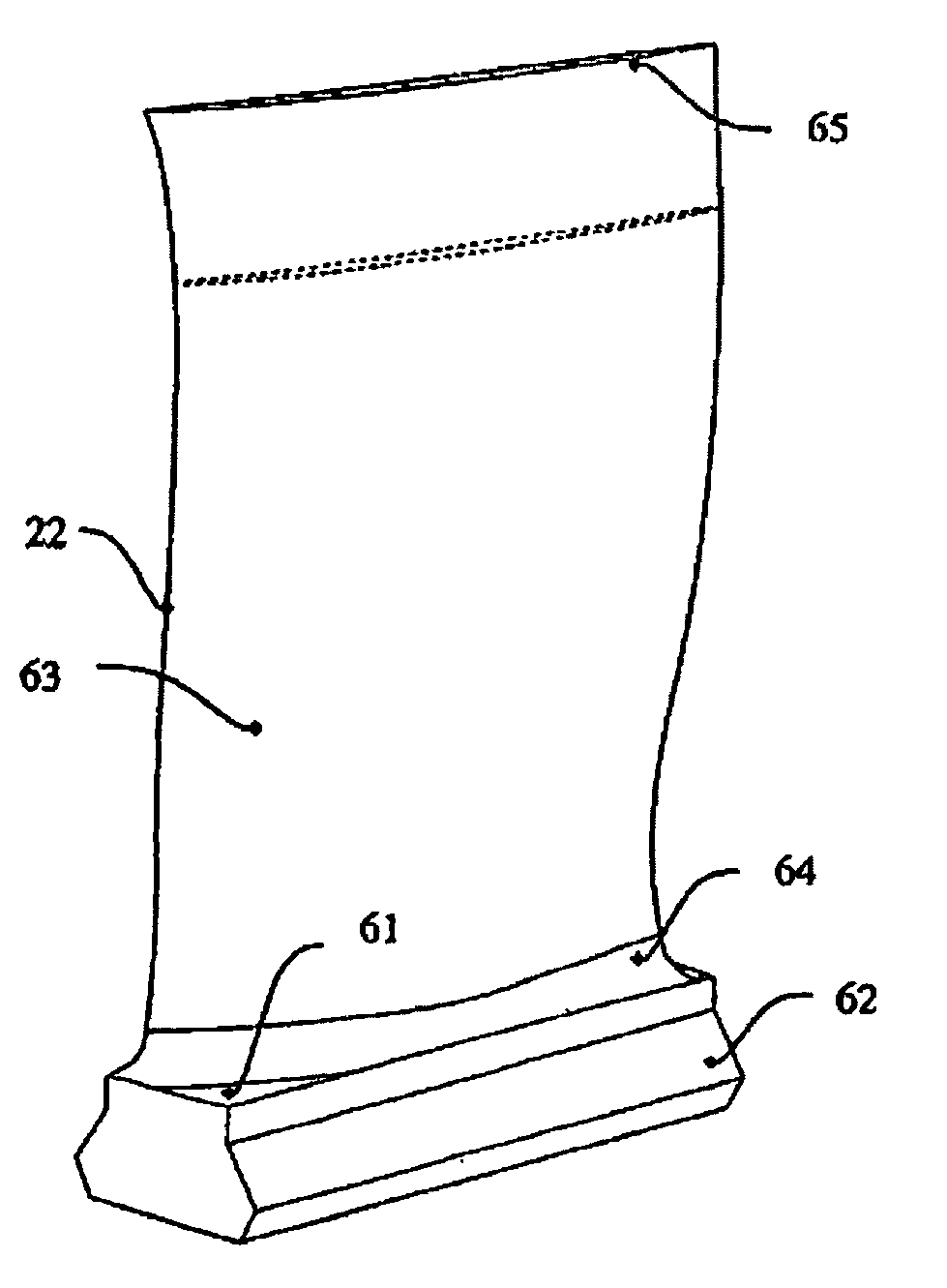
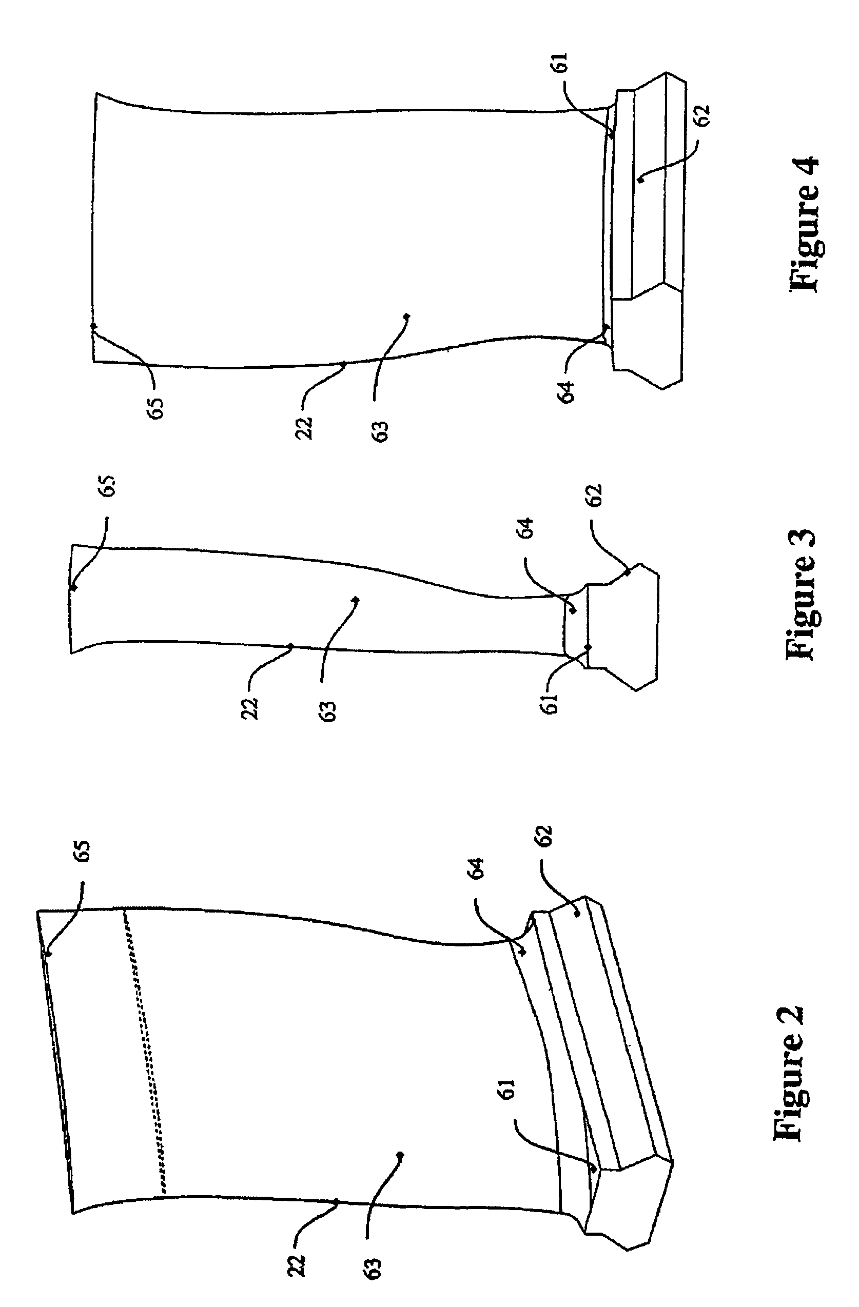
[0014]In accordance with one embodiment of the instant invention, an article of manufacture has a nominal profile substantially in accordance with Cartesian coordinate values of X, Y and Z set forth in TABLE A, and wherein X and Y are distances in inches which, when connected by smooth continuing arcs, define airfoil profile sections at each distance Z in inches, the profile sections at the Z distances being joined smoothly with one another to form a complete airfoil shape.

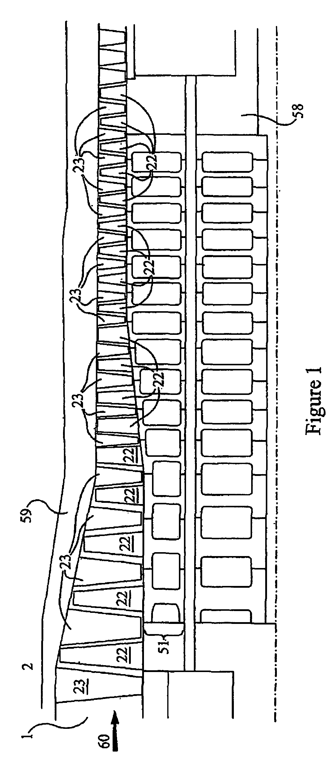
[0015]In accordance with one embodiment of the instant invention, there is provided an airfoil compressor shape for a blade of a gas turbine that enhances the performance of the gas turbine. The airfoil shape hereof also improves the interaction between various stages of the compressor, while simultaneously reducing stage airfoil thermal and mechanical stresses.

[0016]The blade airfoil profile, as embodied by the invention, is defined by a unique loci of points to achieve the necessary efficiency and loading requir...


PUM


Abstract

An article of manufacture having a nominal profile substantially in accordance with Cartesian coordinate values of X, Y and Z set forth in TABLE A. X and Y are distances in inches which, when connected by smooth continuing arcs, define airfoil profile sections at each distance Z in inches. The profile sections at the Z distances can be joined smoothly with one another to form a complete airfoil shape.

Description

BACKGROUND OF THE INVENTION[0001]The present invention relates to airfoils for a blade of a gas turbine. In particular, the invention relates to compressor airfoil profiles for a “Stage 0” rotor blade.[0002]In a gas turbine, many system requirements should be met at each stage of a gas turbine's flow path section to meet design goals. A turbine hot gas path requires that the compressor airfoil rotor blade meet design goals and desired requirements of efficiency, reliability, and loading. For example, and in no way limiting of the invention, a blade of a compressor rotor should achieve thermal and mechanical operating requirements for that particular stage.[0003]Past efforts to meet design goals and desired requirements have provided coatings on the airfoil, but the coatings may not be robust enough or permanent to provide design goals and desired requirements. Accordingly, it is desirable to provide an airfoil configuration with a profile meet to design goals and desired requirement...

Claims


Application Information

Patent Timeline
Patent Type & Authority Patents(United States)
IPC IPC(8): F01D5/14
CPCF01D5/141F05D2250/74
Inventor BONINI, ERIC R.TIPTON, THOMAS R.BUSBEY, BRUCE C.LAMASTER, CHRISTOPHER E.LUMPKIN, JAMIE D.
Owner GE INFRASTRUCTURE TECH INT LLC
Why Eureka
Try Eureka