
Head window fixture and method

a head window and fixture technology, applied in the field of submarine head window manufacturing, can solve the problem of not disclosing a suitable fixtur

Inactive Publication Date: 2012-06-19
THE UNITED STATES OF AMERICA AS REPRESENTED BY THE SECRETARY OF THE NAVY
View PDF13 Cites 13 Cited by
  • Summary
  • Abstract
  • Description
  • Claims
  • Application Information

AI Technical Summary

Benefits of technology

The present invention provides an improved head window potting fixture and method of use for a periscope system. The fixture includes a baseplate and a clamping plate with a plurality of guide members for precise movement. The clamping plate has a recessed portion around the opening for easy installation and removal of the window. The fixture also includes springs and gages for accurate measurement of the relative movement between the clamping plate and the baseplate. The method involves connecting the clamping plate to the baseplate, bonding the window to the clamping plate, and disconnecting and reconnecting the clamping plate and window. The invention allows for easy and accurate installation and removal of the head window in a periscope system.

Problems solved by technology

The above cited prior art does not disclose a suitable fixture for use during construction involving mounting a head window for a periscope system within a suitable frame.

Method used


Image

  • Head window fixture and method
  • Head window fixture and method
  • Head window fixture and method

Examples


Embodiment Construction

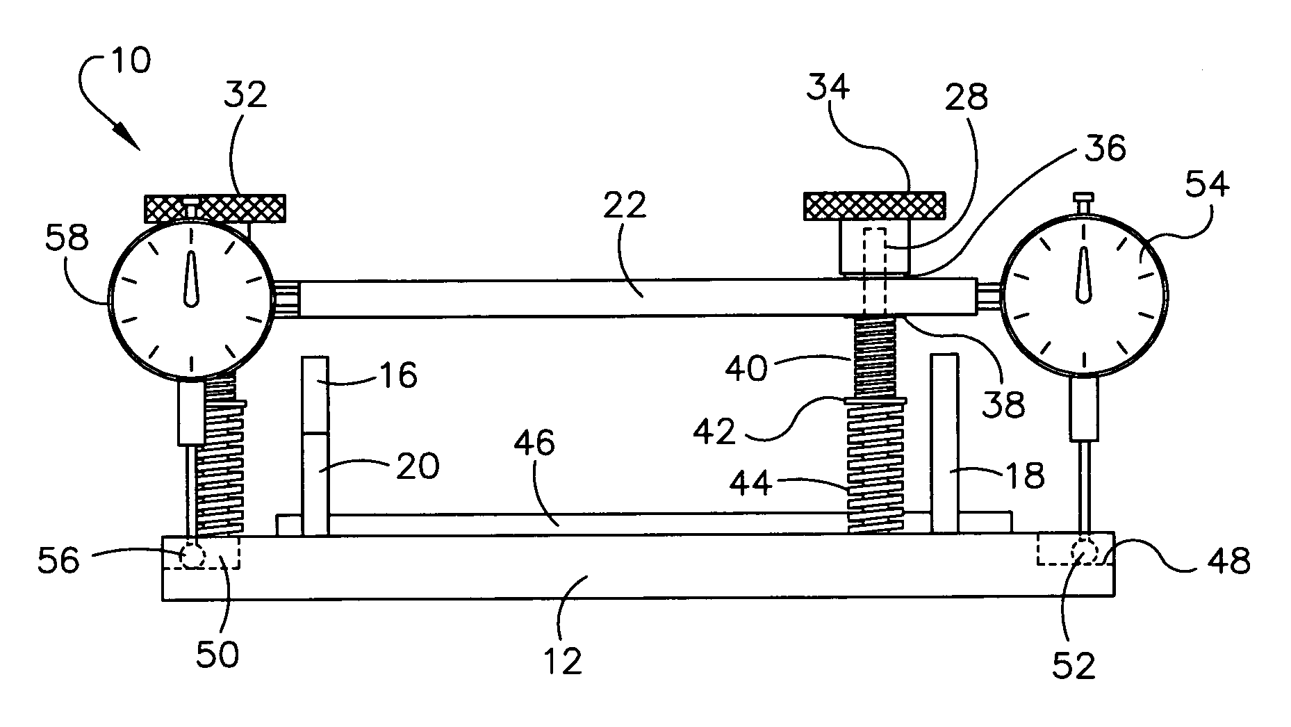
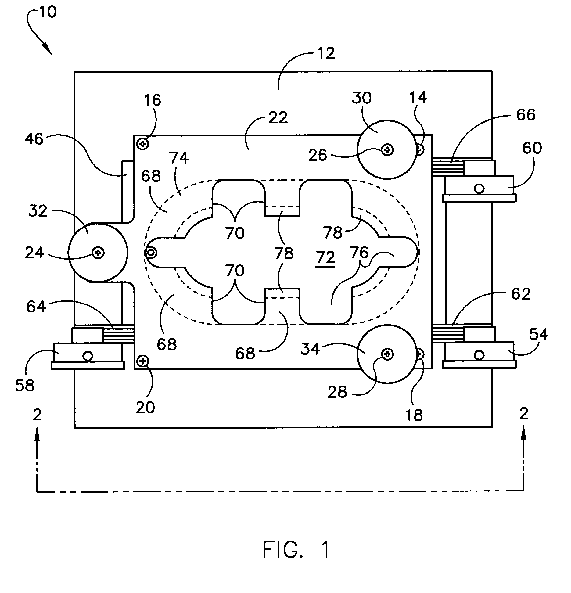
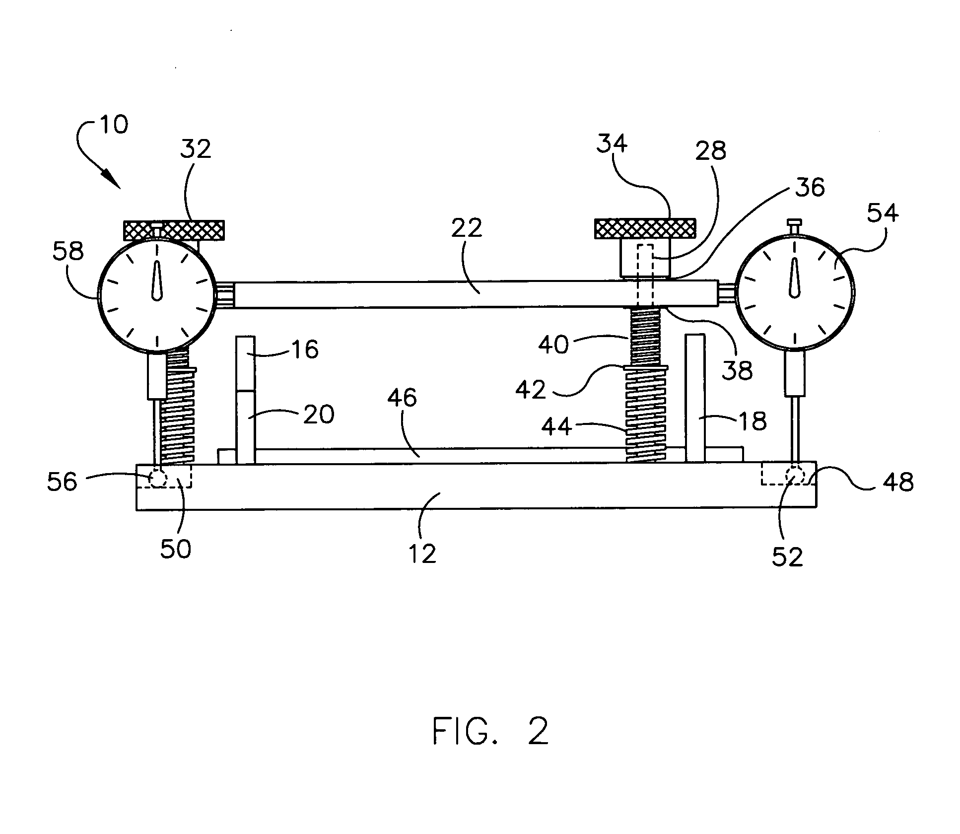
[0032]In one possible embodiment, the present invention is directed to a fixture 10 for providing a mounting foundation for the head window frame and / or to help form a mold for the potting material. The fixture 10 may be utilized to establish a critical thickness space that forms a gap to cushion the head window against sea pressures. In one possible embodiment, the fixture 10 may serve to hold the head window such that once the critical gap is established, then the head window can be removed and reinstalled to the same dimension repeatably. In another possible embodiment of the present invention, the fixture 10 may hold all the components in position until final cure of the potting material is attained.

[0033]Baseplate 12 acts as a foundation for the fixture 10 upon which all the relevant components are supported. Clamping plate 22 may be mounted above the baseplate 12. In one possible embodiment, four dowel pins, such as dowel pins 14, 16, 18, and 20 may be pressed into the basepla...


PUM

PropertyMeasurementUnit
perimeteraaaaaaaaaa
relative movementaaaaaaaaaa
critical thicknessaaaaaaaaaa

Abstract

The present invention provides a fixture and method for mounting a head window to a frame for use in a submarine periscope system. The fixture supports the head window during the potting of the head window to the frame. A spring-loaded clamping plate is mountable to a baseplate for relative movement therebetween. The clamping assembly has an oval recessed portion. A plurality of spaced apart feet are formed within the oval. The feet support and are bonded to the head window. Shim stock are placed between the feet to define a critical gap.

Description

STATEMENT OF GOVERNMENT INTEREST[0001]The invention described herein may be manufactured and used by or for the Government of the United States of America for governmental purposes without the payment of any royalties thereon or therefore.CROSS REFERENCE TO OTHER RELATED APPLICATIONS[0002]None.BACKGROUND OF THE INVENTION[0003]1. Field of the Invention[0004]The present invention relates generally to manufacturing of head windows for submarines and more particularly to a fixture utilized during manufacture of the head window.[0005]2. Description of the Prior Art[0006]During manufacture of a head window for a submarine periscope system, a critical thickness space should be established between the glass window and the wall of a frame for the glass window. The critical thickness space forms a gap that cushions the head window against sea pressures. Uniform thickness of the critical thickness space is essential.[0007]The following U.S. patents describe various prior art fixtures.[0008]U.S...

Claims


Application Information

Patent Timeline
Patent Type & Authority Patents(United States)
IPC IPC(8): B25B5/10B23P11/00B23Q3/18
CPCG02B23/22Y10S269/90Y10T29/53961Y10T29/49998Y10T29/4984
Inventor MACIEJEWSKI, WENDELL C.SASKO, DOUGLASMOTIN, GARY N.
Owner THE UNITED STATES OF AMERICA AS REPRESENTED BY THE SECRETARY OF THE NAVY
Learn More