Eureka AIR delivers breakthrough ideas for toughest innovation challenges, trusted by R&D personnel around the world.

Baler pre-cutter rotor design having reinforced tines

a technology of rotors and rotors, which is applied in the field of rotors with reinforced tines, can solve the problems of bending resistant materials, knife and strippers being damaged as well, and suffering further damage to the bent tines,

Active Publication Date: 2012-06-26
DEERE & CO
View PDF11 Cites 25 Cited by
  • Summary
  • Abstract
  • Description
  • Claims
  • Application Information

AI Technical Summary

Benefits of technology

[0006]According to the present invention, there is provided an improved pr...

Problems solved by technology

A drawback of these prior art pre-cutter arrangements is that the rotor tines are vulnerable to being bent by rocks that are carried with the windrow of crop fed into the rotors for engagement by the tines, with these bent tines being problematic in that they may come into contact with the stationary counter knives and / or crop strippers, which may result not only in the bent tine suffering further damage, but may result in the knives and strippers being damaged as well.
Bend resistant materials are costly and are hard to weld.
Thicker tines result in fewer knives being present over a given width dimension of the rotor, resulting not only in less reduction of the material which passes through the pre-cutter arrangement, but also results in an increase in the weight of the pre-cutter arrangement, thus requiring additional horsepower to propel the machine carrying the pre-cutter arrangement.
The problem to be solved then is that of providing a pre-cutter rotor having tines which are relatively stiff, but do not add weight to the rotor, and which do not require a reduction in the number of stationary cutter knives that cooperate with the rotor tines over a given width dimension of the pre-cutter arrangement.

Method used


Image

  • Baler pre-cutter rotor design having reinforced tines
  • Baler pre-cutter rotor design having reinforced tines
  • Baler pre-cutter rotor design having reinforced tines

Examples


first embodiment

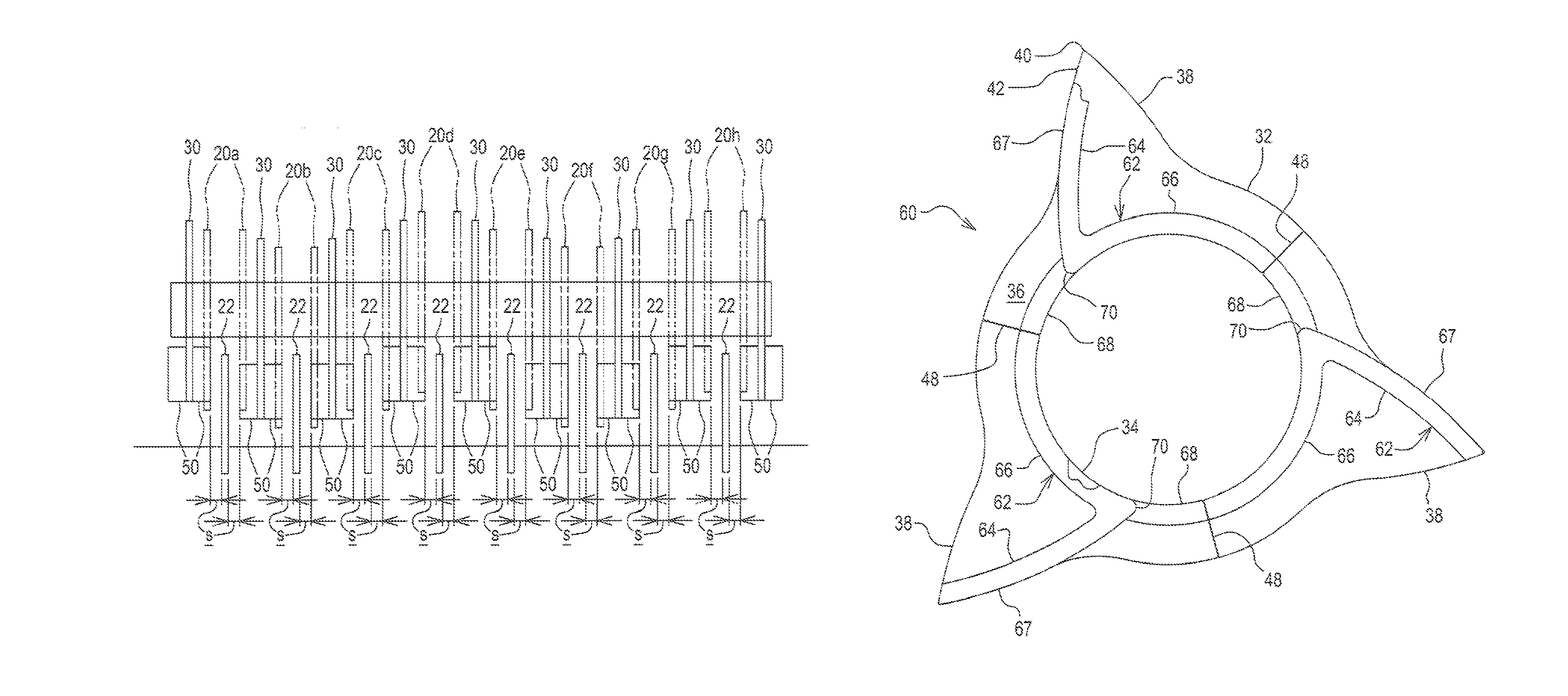
[0024]Referring to FIGS. 4 and 5, there is shown a tine 30 constructed in accordance with the present invention. The tine 30 includes a flat plate 32 in the form of a star including a centrally located, circular mounting hole 34 surrounded by a ring-shaped mounting portion 36 to which a plurality of radially extending crop-engaging points 38 are joined at equal-angularly spaced locations about the center of the hole 34. Although they need not be, the points 38 are each formed symmetrically about a radial line L extending between the axis of the hole 34 and a tip 40 of the point. For the sake of discussion, the forward direction of rotation F of the tine 30 is considered to be counterclockwise, as indicated by the arrow in FIG. 4. When considered relative to the forward direction of rotation F, each crop-engaging point 38 of the tine 30 has a leading-edge including an outer convexly curved section 42 which extends inwardly from the tip 40 of the point and is joined to a concavely cur...

second embodiment

[0027]Referring now to FIG. 7, there is shown tine 60 constructed in accordance with the invention which differs from the tine 30 in that pairs of reinforcing straps 62 are used in place of the pairs of straps 50. The pairs of straps 62 each include a first section 64 shaped and located like the pairs of straps 50, and include a second section 66 joined to, and extending in trailing relationship to, the first section 64, the second section 66 being curved about the axis of the hole 34 so as to reinforce a region of the mounting ring 32 bordering the hole 34. Each of the first sections 64 has a curved leading edge 67 which forms a lateral extension of the curved leading edge of the tine point 38. Like the tine 30, the plate 32 of the tine 60 is constructed in thirds, with ends of the second section 66 of each pair of reinforcing straps 62 terminating so as to be coincident with the welded ends 48 of the three sections of the mounting ring 36, thus leaving a gap between adjacent ones ...

third embodiment

[0028]Referring now to FIG. 8, there is shown a tine 72, which is constructed in accordance with the invention similar to the tine 30 shown in FIG. 4, but differing in that a sheet metal strap is formed to define an arcuately shaped ramp 74 that borders a region of the hole 34 in leading relationship to an inner end of that one of each of the pair of straps 50 which is on the side of the tine 72 that would face an adjacent one of the knives 22 when forming part of an installed rotor 60 (see FIG. 6). The ramp 74 is slopped axially outwardly form the mounting ring 36 of the plate 30 and has a leg 76 at its trailing end which abuts the leading edge 52 of the strap 50 at a height from the mounting ring 36 approximately equal to that of the strap 50. Thus, the ramps 74 each operate to engage crop and deflect it axially toward the adjacent knife 22 as the leading edge 52 of the strap 50 engages the crop and carries it for being cut by the knife 22.

[0029]FIG. 9 shows a third of a tine 80, ...


PUM


Abstract

Tines of a baler pre-cutter rotor each include a plate having a plurality of points disposed at equally spaced locations about a rotation axis of the rotor, with each point having a leading region reinforced by a pair of straps fixed in sandwiching relationship to the point. In one embodiment, the pair of straps is also applied to opposite sides of a trailing region bordering a circular mounting hole of the plate. In another embodiment, a second pair of straps abuts each first pair of straps and reinforces a leading region bordering the circular mounting hole. Instead of the second pair of straps, a ramp may be provided on a side surface of the plate for deflecting crop towards a pre-cutter stationary cutting knife. Instead of including separate straps, the tines can be cast or forged as identical sections including a tine point.

Description

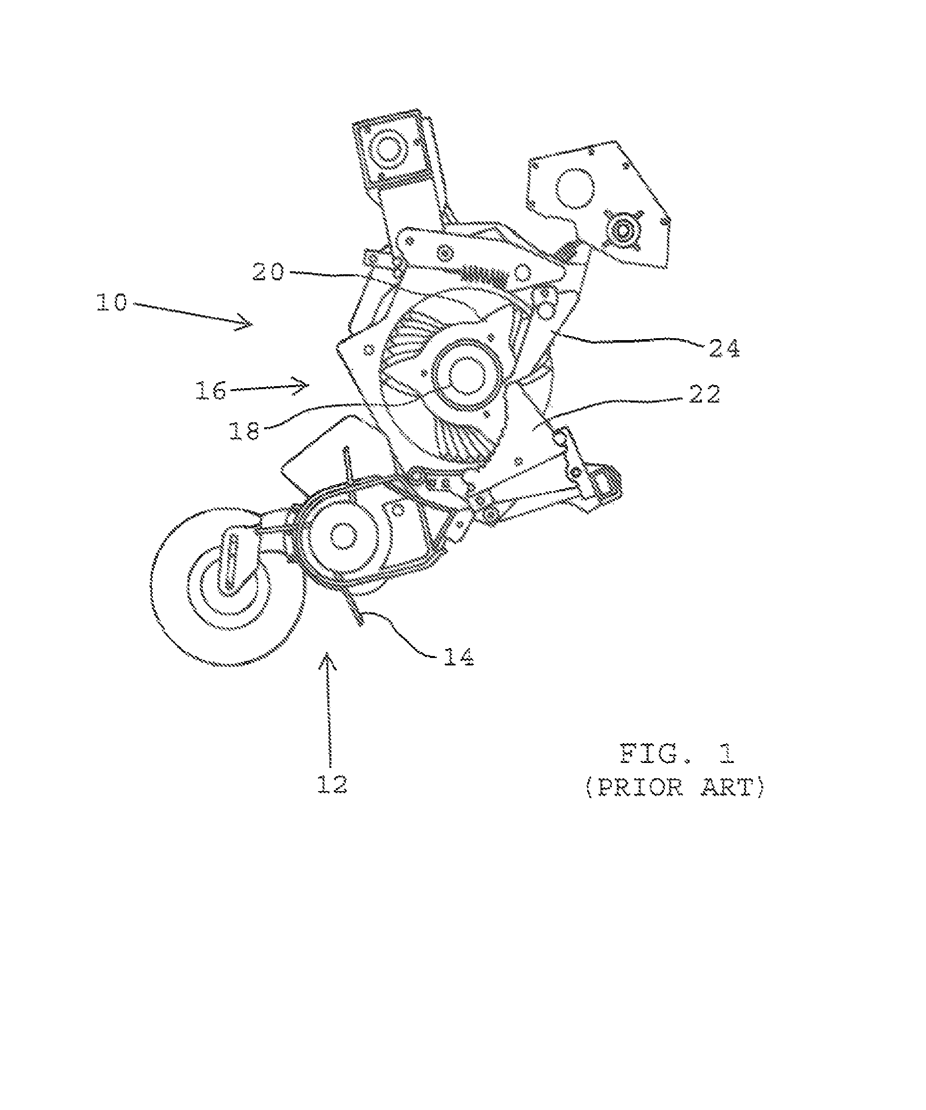
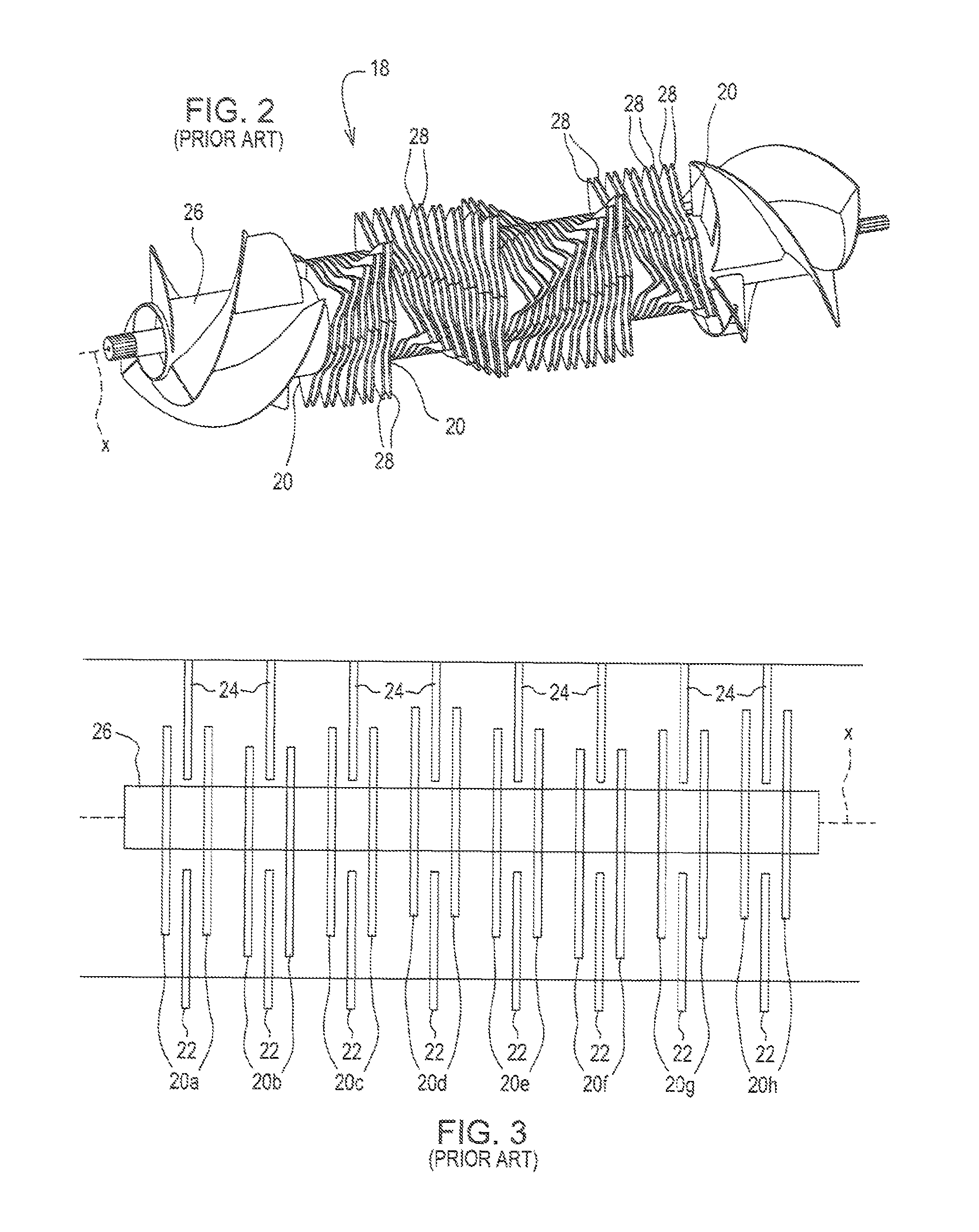
FIELD OF THE INVENTION[0001]The present invention relates to pre-cutter arrangements for agricultural crop gathering machines, and more particularly, relates to tines for the rotors of such pre-cutter arrangements.BACKGROUND OF THE INVENTION[0002]Current pre-cutter arrangements include rotors having tines constructed of planar metal plates mounted in spaced, parallel relationship along a length of a cylindrical rotor member, the tines each including a plurality of crop-engaging points arranged equal-angularly about a rotation axis of the rotor member. The tines are arranged to sweep parallel paths located on opposite sides of stationary cutter knives and crop strippers. U.S. Pat. Nos. 7,694,504 and 6,595,123 disclose pre-cutter arrangements of this type.[0003]A drawback of these prior art pre-cutter arrangements is that the rotor tines are vulnerable to being bent by rocks that are carried with the windrow of crop fed into the rotors for engagement by the tines, with these bent tine...

Claims


Application Information

Patent Timeline
IPC IPC(8): A01D39/00A01D43/02A01D75/00
CPCA01D90/04A01F15/10A01F29/02A01F2015/108
Inventor LANG, ERIC R.SCHLESSER, WALTER M.
Owner DEERE & CO
Why Eureka
Eureka Blog
Learn More