Inkjet print head and print element substrate for the same

a technology of print element and print head, which is applied in the direction of printing, metal-working equipment, writing implements, etc., can solve the problems of deteriorating electrical reliability and and achieve the effect of improving electrical reliability of print head

Inactive Publication Date: 2012-06-26
CANON KK
View PDF4 Cites 0 Cited by
  • Summary
  • Abstract
  • Description
  • Claims
  • Application Information

AI Technical Summary

Benefits of technology

[0015]Accordingly, an object of the present invention is to improve electrical reliability of a print head by preventing occurrence of a region where an air bubble exists or where a sealing member (first sealant) is not filled.
[0025]Therefore, any communication with ambient air does not occur in heating of sealant hardening after another sealing member (second sealant) is applied, thereby reducing the possibility of deterioration of electrical reliability of the print head due to conduction by ink. Further, there can be prevented also occurrence of the problem that a crack is produced in the sealant by an external force applied at print operating after mounting the print head to the printing apparatus, breaking insulated condition. As a result, the reliability of the print head can be improved.

Problems solved by technology

Then, inflow of ink may occur, possibly deteriorating electrical reliability of the print head.
In addition, a crack may be generated in the sealant by an external force applied at print operating after mounting the print head to the printing apparatus, possibly causing the deterioration of electrical reliability, similarly.

Method used


Image

  • Inkjet print head and print element substrate for the same
  • Inkjet print head and print element substrate for the same
  • Inkjet print head and print element substrate for the same

Examples


second embodiment

(3) Second Embodiment

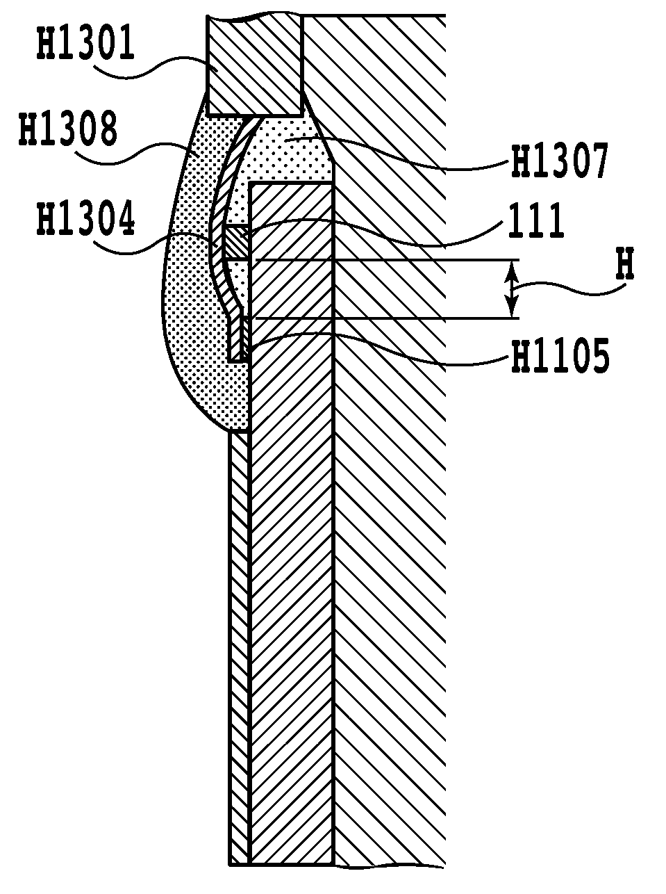
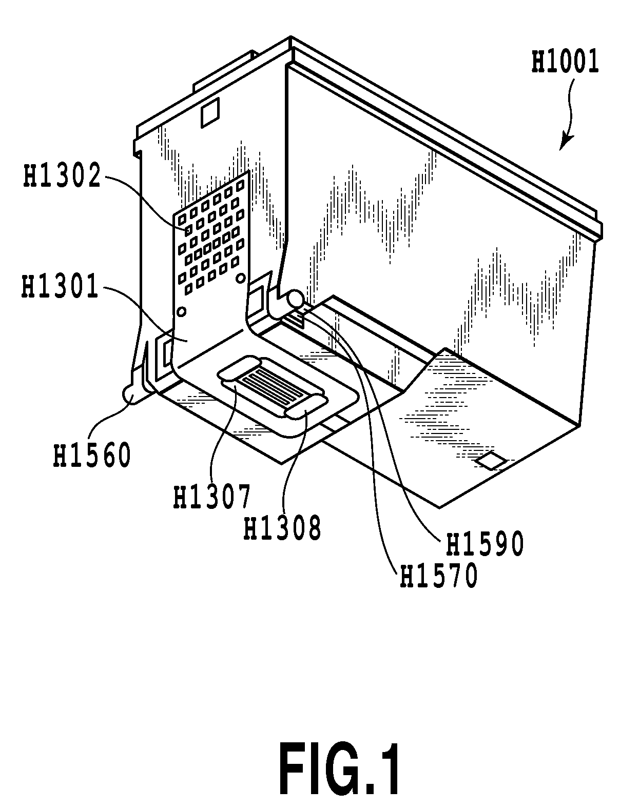
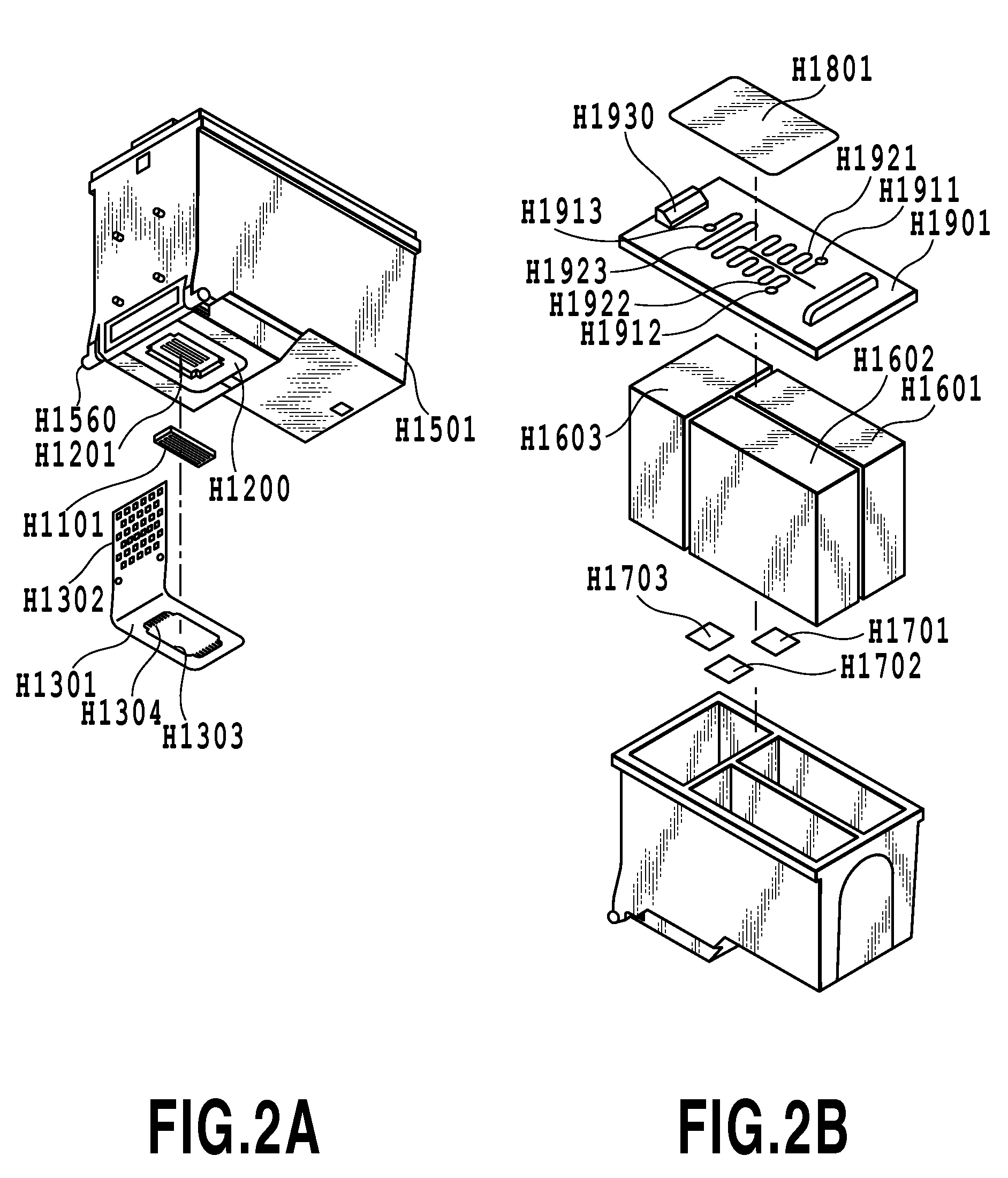
[0078]By referring to FIGS. 11 and 12, the characteristic construction of the second embodiment in the present invention will be explained in detail. FIG. 11 is a schematic plan view of a print element substrate according to the second embodiment. FIG. 12 is a schematic plan view showing the connecting portion between the print element substrate and an electrical wiring tape. Components identical to those in the first embodiment are referred to as identical reference symbols.

[0079]In the first embodiment, the construction where the electrode terminals H1105 of the print element substrate H1101 each having an equal width and the lead terminals H1304 of the electrical wiring tape H1301 each having an equal width are arranged as having an equal clearance has been described. However, the present invention can be applied as shown in FIG. 11 and FIG. 12 even in a case where each width and each clearance of each of the electrode terminals H1105 and the lead terminals H...


PUM

PropertyMeasurementUnit
thicknessaaaaaaaaaa
lengthaaaaaaaaaa
widthaaaaaaaaaa

Abstract

An inkjet print head is provided with a plurality of electrode terminals connected to a plurality of connecting terminals extending from electrical wiring members transmitting drive signals of elements generating energy for ejecting ink, and an insulating portion for insulating the extending portion of the connecting terminal to the connecting portion where the connecting terminal is connected to the electrode terminal from the print element substrate, the connecting portion being sealed by a sealant spreading due to a capillary force between the plurality of the connecting terminals. In order to prevent occurrence of the non-existence region of the sealant due to the blocking of the sealant by the insulating portion, the insulating portion is constructed of a plurality of separated convex portions in contact with the plurality of the connecting terminals respectively to form a groove between the convex portions for allowing the passing of the sealant.

Description

BACKGROUND OF THE INVENTION[0001]1. Field of the Invention[0002]The present invention relates to an inkjet print head used in an inkjet printing apparatus for ejecting a liquid such as ink to perform a print operation and a print element substrate for such an inkjet print head. It should be noted that the inkjet print head of the present invention may be applied not only to general printing apparatuses, but also to copying machines, facsimile machines with communication systems, apparatuses such as word processors with print units, or multifunction printers made of a combination with these apparatuses.[0003]2. Description of the Related Art[0004]The construction of the inkjet print head (hereinafter, simply called a print head also) used in the inkjet printing apparatus is disclosed in Japanese Patent Laid-Open No. H06-023997 (1994) or the like.[0005]As the main component of the print head disclosed in Japanese Patent Laid-Open No. H06-023997 (1994), there is a print element substra...

Claims


Application Information

Patent Timeline
Patent Type & Authority Patents(United States)
IPC IPC(8): B41J2/06
CPCB41J2/14072B41J2/1603B41J2/1631B41J2/1643B41J2/1623Y10T29/49401
Inventor FUKUI, SHIGEKI
Owner CANON KK
Why Eureka
Try Eureka