Door seal system for steam sterilizer

a technology for sealing doors and steam sterilizers, applied in the field of sterilizer, can solve problems such as leakage around the seal and compromise of the seal around the door

Active Publication Date: 2012-06-26
AMERICAN STERILIZER CO
View PDF6 Cites 6 Cited by
  • Summary
  • Abstract
  • Description
  • Claims
  • Application Information

AI Technical Summary

Benefits of technology

[0007]An advantage of the present invention is a door-seal system for creating an active seal around a door of a steam sterilizer.
[0008]Another advantage of the present invention is a door-seal system as described above that establishes an external pressure force to seal the door of a steam sterilizer.
[0009]Another advantage of the present invention is a door-seal system as described above for use in a high-level contamination facility.
[0010]Another advantage of the present invention is a door-seal system as described above that includes a back-up pressure source to maintain a pressure force against a seal element for a predetermined period of time, following loss of customer-supplied utilities to the sterilizer.
[0011]Another advantage of the present invention is a door-seal system as described above that includes sensors and controls that insure that the seal around a door on a steam sterilizer will remain sealed under a large variety of failure conditions.
[0012]Another advantage of the present invention is a door-seal system as described above that constantly monitors itself for failures and malfunctions.

Problems solved by technology

However, once the chamber is pressurized, the door is forced away from the end frame of the sterilizer, which may result in a potential leak around the seal.
Because of the foregoing problem, and because of the cost and complexity of most manually operated mechanical seals, sterilizer technology has moved away from traditional passive seals to “active seals,” wherein an external pressure force, typically steam or air, is used to apply a pressure to accomplish sealing.
A problem with active seals is that the seal around the door may be compromised if the external pressure force is lost.

Method used


Image

  • Door seal system for steam sterilizer
  • Door seal system for steam sterilizer
  • Door seal system for steam sterilizer

Examples


Embodiment Construction

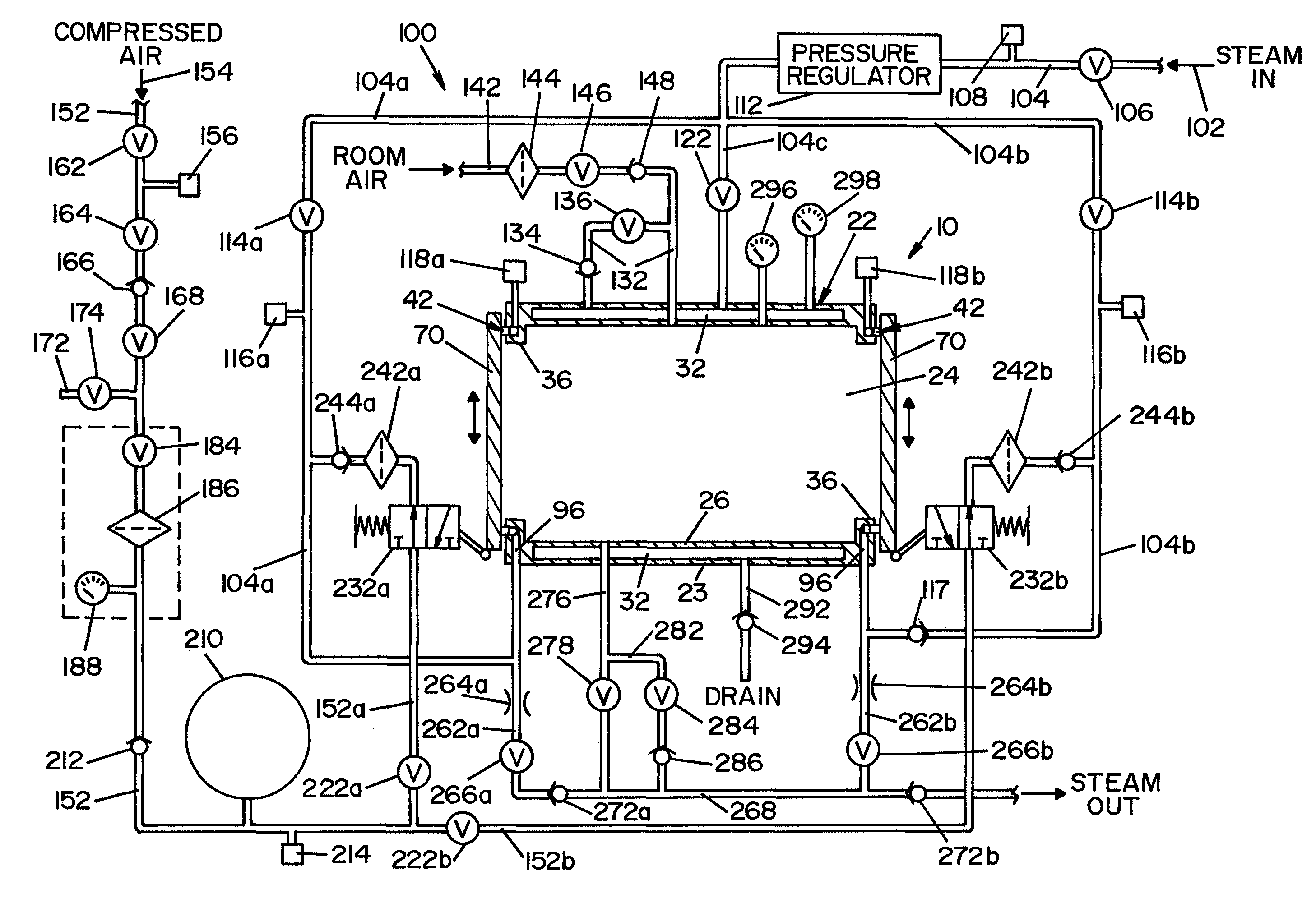
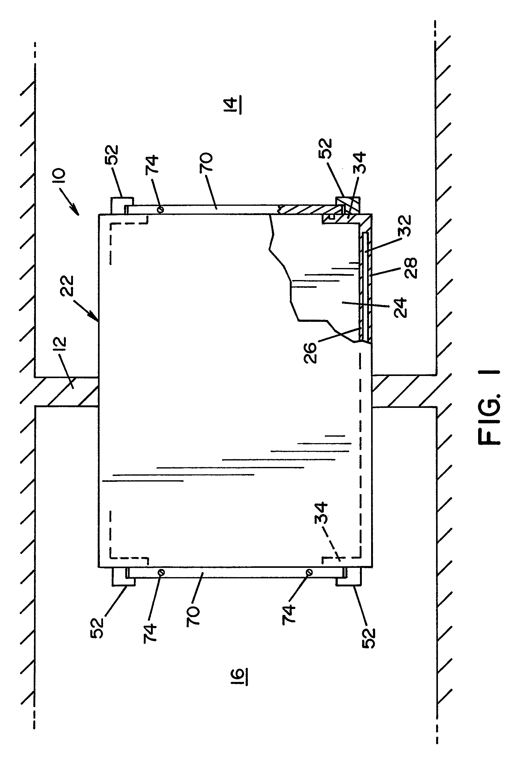
[0027]Referring now to the drawings wherein the showings are for the purpose of illustrating a preferred embodiment of the invention only and not for the purpose of limiting same, FIG. 1 shows a top plan view of a steam sterilizer 10. FIG. 1 is a partially sectioned, top plan view of steam sterilizer10, showing steam sterilizer 10 disposed within a wall 12 that divides a “contaminated room”14 from a “clean room”16. As used herein, the term “contaminated room” refers to a room where contaminated articles or objects to be sterilized are located prior to sterilization. The term “clean room” refers to a room wherein articles or goods sterilized in sterilizer 10 may be removed for further handling following a sterilization cycle.

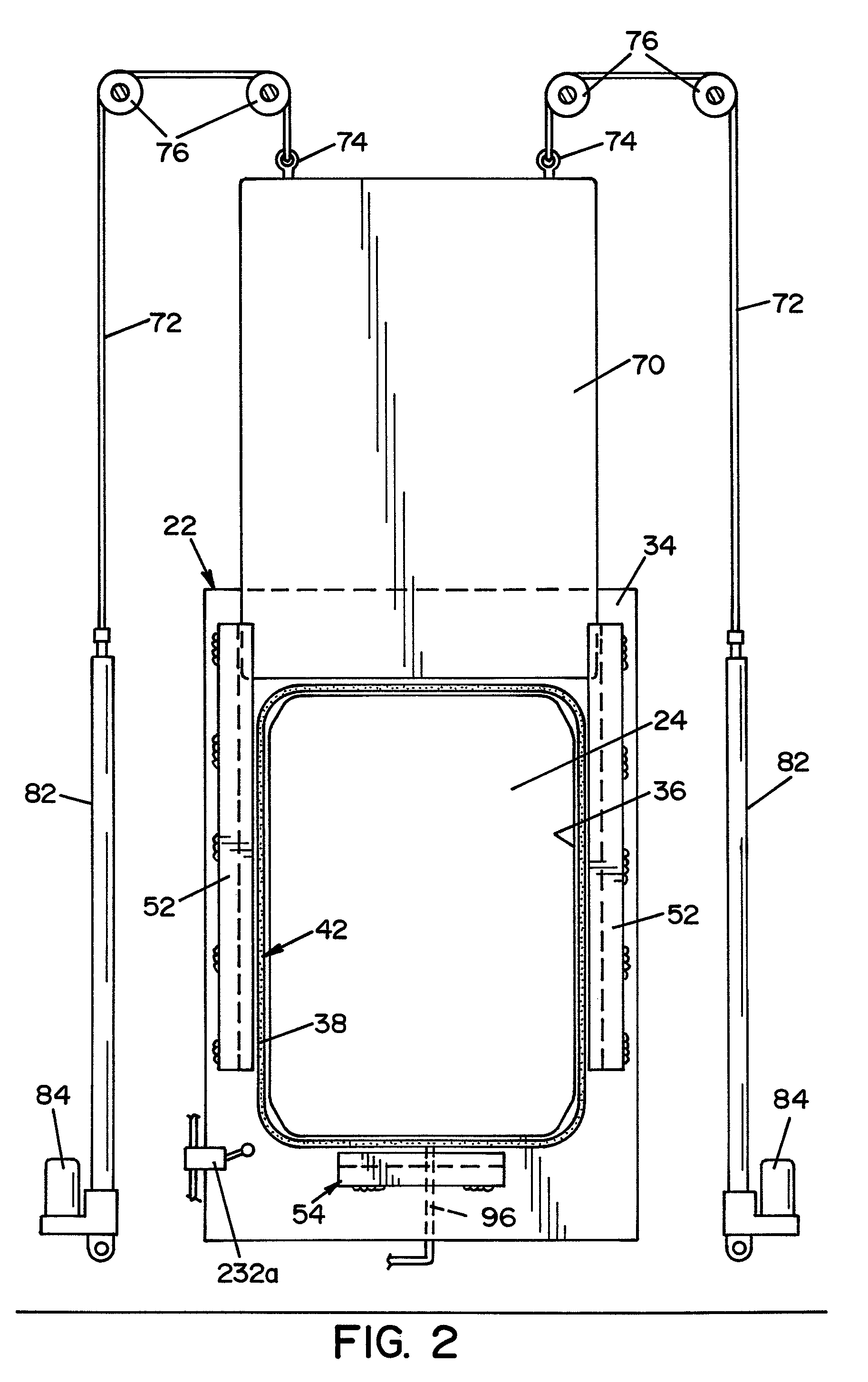
[0028]Sterilizer 10 is basically comprised of a body 22 defining an internal sterilization chamber 24. In the embodiment shown, sterilizer body 22 is generally rectangular in shape. Sterilizer body 22 is defined by an inner wall 26 and an outer wall 28. Outer wal...


PUM

PropertyMeasurementUnit
pressureaaaaaaaaaa
forceaaaaaaaaaa
mechanical forceaaaaaaaaaa

Abstract

The present invention provides a sterilizer having a housing defining a sterilization chamber. An opening in the housing communicates with the chamber. A surface surrounds the opening, and a door is movable between one of an open position allowing access to the chamber through the opening and a closed position covering the opening. A seal element is associated with the surface for forming a fluid-tight seal between the door and the surface when the door is in the closed position. An operating system is provided for applying pressure to one side of the seal from a first source external to the operating system to force the seal into engagement with the door. Sensing means are provided for monitoring the pressure applied to the seal from the first pressure source. A second source of pressure is provided in the operating system and is connectable to the seal. Valve means connect the pressure source to the steam system if the sensing means detects a pressure below a set pressure sufficient to sustain a seal between the door and the surface.

Description

FIELD OF THE INVENTION[0001]The present invention relates generally to sterilizers and, more particularly, to a system for sealing doors on a steam sterilizer.BACKGROUND OF THE INVENTION[0002]Steam sterilizers are well known and widely used in hospitals, laboratories, and other facilities for sterilizing and decontaminating many types of articles. For steam sterilizers installed in high-level containment facilities that work with agents that are potentially life threatening, it is important that the doors on the sterilizer be kept sealed in the event of a utility failure, so as to prevent contaminants in the chamber from being released.[0003]In the past, a “passive” or “crush” seal arrangement has been the accepted standard for steam sterilizer door seals. A passive seal is made by mechanically applying a force to the door to force the door into engagement with the sterilizer chamber. Typically, the mechanical force is applied by a manually operated screw mechanism that keeps the do...

Claims


Application Information

Patent Timeline
Patent Type & Authority Patents(United States)
IPC IPC(8): A61L2/00E06B7/18
CPCA61L2/07A61L2/26
Inventor BUCZYNSKI, PETER J.HUBER, JAMES M.KARLE, DAVID A.NURMINEN, TEPPOMCCALL, DAVID F.
Owner AMERICAN STERILIZER CO
Why Eureka
Try Eureka