Glass block panel system and fabrication method of same

a glass block and panel technology, applied in the direction of resiliently mounted floors, flooring, window/door frames, etc., can solve the problems of difficult to properly position the glass, the construction of glass brick structures using mortar requires a great deal of skill and experience, and the inability to see objects beyond the glass

Inactive Publication Date: 2006-05-16
LEMERT STEVEN G
View PDF45 Cites 7 Cited by
  • Summary
  • Abstract
  • Description
  • Claims
  • Application Information

AI Technical Summary

Benefits of technology

[0015]The supporting side arms of the peripheral frame members, the cross-arms of the internal frame spacers, and the cross-arms of the facing strips each may have a flexible extrusion coupled along and extending outwardly from each of the exposed ends (tips) thereof. The flexible extrusions may be in an angled position. In this way, the flexible extrusions may flex back from their bent position while abutting the installed glass blocks, thereby creating a seal between the blocks and the extrusions. Thus, the length, angle, and especially the flexibility of the flexible extrusions allow them to compensate for virtually any gap between the installed blocks and the extrusions while still forming a seal between the blocks and the extrusions.

Problems solved by technology

Windows, walls, and other partitions have long been formed from glass blocks which admit the passage of light but, because of their thickness, do not permit a clear view of objects beyond the glass.
The conventional construction of a glass brick structure using mortar is a task that requires a great deal of skill and experience.
Without such experience, it is difficult to properly position the glass blocks so that they lie in level courses and so that they are securely held in place within the structure.
These requirements substantially increase the expense and difficulty that attends the installation of a glass block structure.
Further, glass brick structures fabricated using mortar are not flexible and do not adequately accommodate settling or other movements that may affect the structure.
Notably, glass blocks tend to have slight variations in geometry that lead to construction difficulties related to spacers.
Thus, when the blocks are installed in a paneled structure, spacers may not create a sufficient seal between block layers due to the variations in the blocks.
When the spacers do not seal the blocks and panels completely, water, dirt, pests, and the like may get into the structure through holes or gaps left in the faulty seal.
Once water gets into the paneled structure, it pools at the bottom of the paneling and thereby fosters mold and unwanted discoloration.
In addition, gaps in the seal lessen the insulating capability of the paneled structure because air may escape through the unwanted orifices.
A further drawback associated with construction of a glass block structure using spacers relates to burdensome fabrication methods corresponding to conventional framework and paneling assemblies.
Then as the block is longitudinally inserted into the framework / paneling from the top of the framework / paneling, the caulking is scraped and smashed down the length of the vertical frames / panels ultimately building up into an unwanted mass of residual sealant.
Thus, conventional construction of glass block structures tends to be messy and arduous and artisans are restricted in the manner by which they may assemble the glass blocks.

Method used


Image

  • Glass block panel system and fabrication method of same
  • Glass block panel system and fabrication method of same
  • Glass block panel system and fabrication method of same

Examples


Embodiment Construction

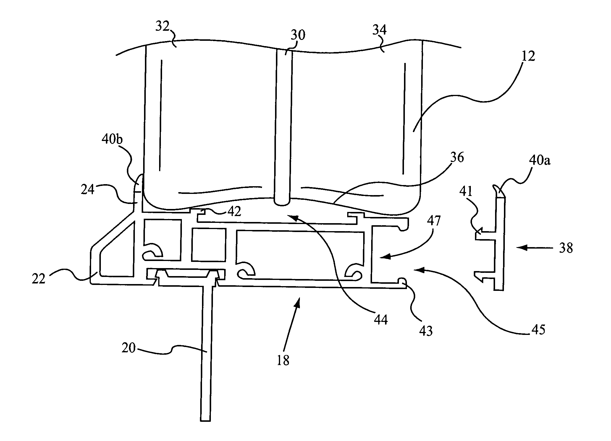
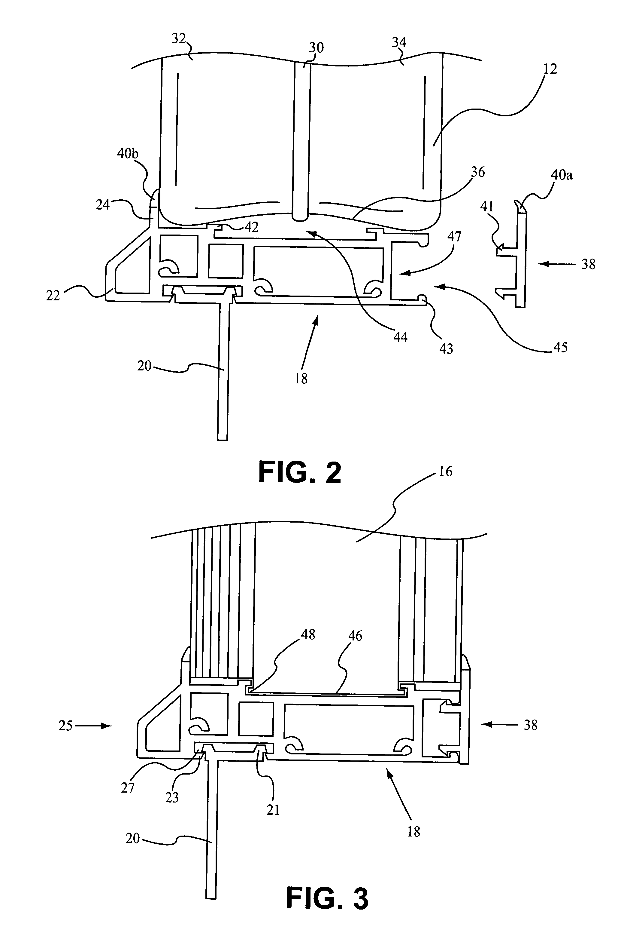
[0028]The invention is particularly useful in facilitating the assembly of compartmentalized frameworks useful in the fabrication of straight or radius glass block panel systems. Generally, straight or radius glass block panel systems according to embodiments of the invention are used in construction of translucent structures included in walls. However, it will be understood by those of ordinary skill in the art that glass block panel systems according to embodiments of the invention are not limited to uses relating to construction of translucent structures included in walls. Rather, those of ordinary skill in the art will also understand that glass block panel systems according to embodiments of the invention may also be used in a variety of applications with similar results for a variety of structures, such as translucent bridges, translucent floors, translucent ceilings, translucent roofs, and the like for structures including, for example: dwellings, commercial buildings, monume...


PUM

PropertyMeasurementUnit
flexibleaaaaaaaaaa
transparencyaaaaaaaaaa
translucencyaaaaaaaaaa

Abstract

A glass block panel system is disclosed that includes glass blocks secured in a framework. The framework includes an external framework having external frame members each of which comprises a base web portion formed between opposing side arms, wherein one of the opposing side arms is removably coupled to the base web portion. The framework also includes an internal framework having internal frame spacers each of which comprises a spacer web portion formed between first and second opposing facing strips, each facing strip comprising cross-arms, wherein at least one of the facing strips is removably coupled to the spacer web portion. The side arms and cross-arms have flexible extrusions protruding from tips thereof. A fabrication method is also disclosed comprising: forming at least a portion of at least one framework compartment; applying adhesive sealant; latitudinally inserting at least one glass block; and completing the glass block panel system.

Description

BACKGROUND OF THE INVENTION[0001]1. Technical Field[0002]This invention generally relates to a glass block panel system and a fabrication method of the same that allows the system to be pre-assembled and shipped to an installation location.[0003]2. Background Art[0004]Glass has many qualities that make it well-suited for use in windows, including transparency or translucency, hardness, imperviousness to the natural elements, insulating properties, and an ability to be formed into various shapes. Windows, walls, and other partitions have long been formed from glass blocks which admit the passage of light but, because of their thickness, do not permit a clear view of objects beyond the glass. Thus, glass block is ideal for any situation or setting where both natural illumination and privacy are important.[0005]Individual glass blocks are assembled into glass block structures by attaching a material to the blocks that bonds the blocks together. This material typically is in the form of...

Claims


Application Information

Patent Timeline
Patent Type & Authority Patents(United States)
IPC IPC(8): E04C1/42E04C2/54E06B1/30E06B1/36E06B3/68
CPCE04C2/546E06B1/36E06B1/30E06B3/68
Inventor LEMERT, STEVEN G.
Owner LEMERT STEVEN G
Why Eureka
Try Eureka