Oval transmission structure

a transmission structure and octagonal technology, applied in the field of octagonal transmission structure, can solve the problems of increasing cost, occupying a large space, and reducing the motivation to continuously operate the exercise device, and achieve the effect of balancing the weight of both users and entire components, stable back-and-forth reciprocation, and favorable transmission

Inactive Publication Date: 2012-07-10
LAI YING CHOU
View PDF10 Cites 6 Cited by
  • Summary
  • Abstract
  • Description
  • Claims
  • Application Information

AI Technical Summary

Benefits of technology

[0011]Preferably, at a rear portion of the oval transmission structure, a track frame is axially disposed for being arranged with a block including at least one slot to form a sloping frame. Alternatively, the track frame could be directly fixed to the block to form a sloping frame. Thereby, the reciprocal treading from the both feet allows the two cranks to axially motivate the front ends of the two transmission shafts for achieving a relative oval action. The axle bolt on the other hand triggers the attached shaft and the sliding wheel thereunder for accomplishing the reciprocal rising and falling motion on the track frame, so that the sliding block is brought about to move the lower portions of the two swaying moving shafts for attaining the relative displacement. The upper portions of the two swaying moving shafts thence sway oppositely, and the treadle frames are axially motivated to slide on the track wheels, thereby allowing the treadles to accordingly rise and fall. Thus, users are able to simulate the mountain climbing action afoot.
[0012]Preferably, the attached shaft pivots to the predetermined position at a side of the lower portion of the shaving shaft so as to connect to the axle bolt of the transmission shaft. Moreover, at two sides of the top end of the oval transmission structure, secondary shafts are pivoted to axle bolts. Thus, in time of the reciprocation being achieved by feet, the two cranks axially motivate the front ends of the two transmission shafts for accomplishing the relative oval actions. Thereby, the axle bolt brings the attached shaft and the secondary shaft to trigger the lower portions of the two swaying moving shafts for attaining the relative displacement. The upper portion of the swaying moving shafts thence sways oppositely so as to pivotally drive the treadle frames to slide on the track wheels. The secondary shaft sways along with a moving route of the push-pull shaft for effectively bearing the weights of both user and entire components. As a result, a stable back-and-forth reciprocation is achieved.

Problems solved by technology

1. The existing oval exercising device provides the back-and-forth treading reciprocating movement in accordance with the predetermined oval rotating scope as well as the swaying scope. The existing oval exercising device is unable to be adjusted for suiting to every individual and his appropriate exercising consumption. Moreover, in time of the initial treading, users have to tread on the treadle beyond an operating threshold limit value to continue the treading. As a result, the existing configuration can merely suit to part of the body.
2. The existing oval exercising device mostly simulates the motion of riding a bicycle. Namely, other interesting exercising manners are hardly to be achieved. Thus, the only bicycle riding motion may be prosaic, thence decreasing the motivation to continuously operate the exercising device. Further, the fundamental base of the exercising device is rather long, thereby occupying large space and increasing the cost.
3. The existing oval exercising device mainly adopts the integral swaying moving shafts. Therefore, the swaying range brought about by both hands and feet would accordingly vary in accordance with the different positions of the axle center. Namely, if the axle center is low, the swaying range of both hands is large while the swaying range of feet is accordingly small. Oppositely, if the axle center is high, the swaying range of both hands is small while the swaying range of feet is accordingly large. Obviously, the existing oval exercising device is unsuited to every age group.

Method used


Image

  • Oval transmission structure
  • Oval transmission structure
  • Oval transmission structure

Examples


Embodiment Construction

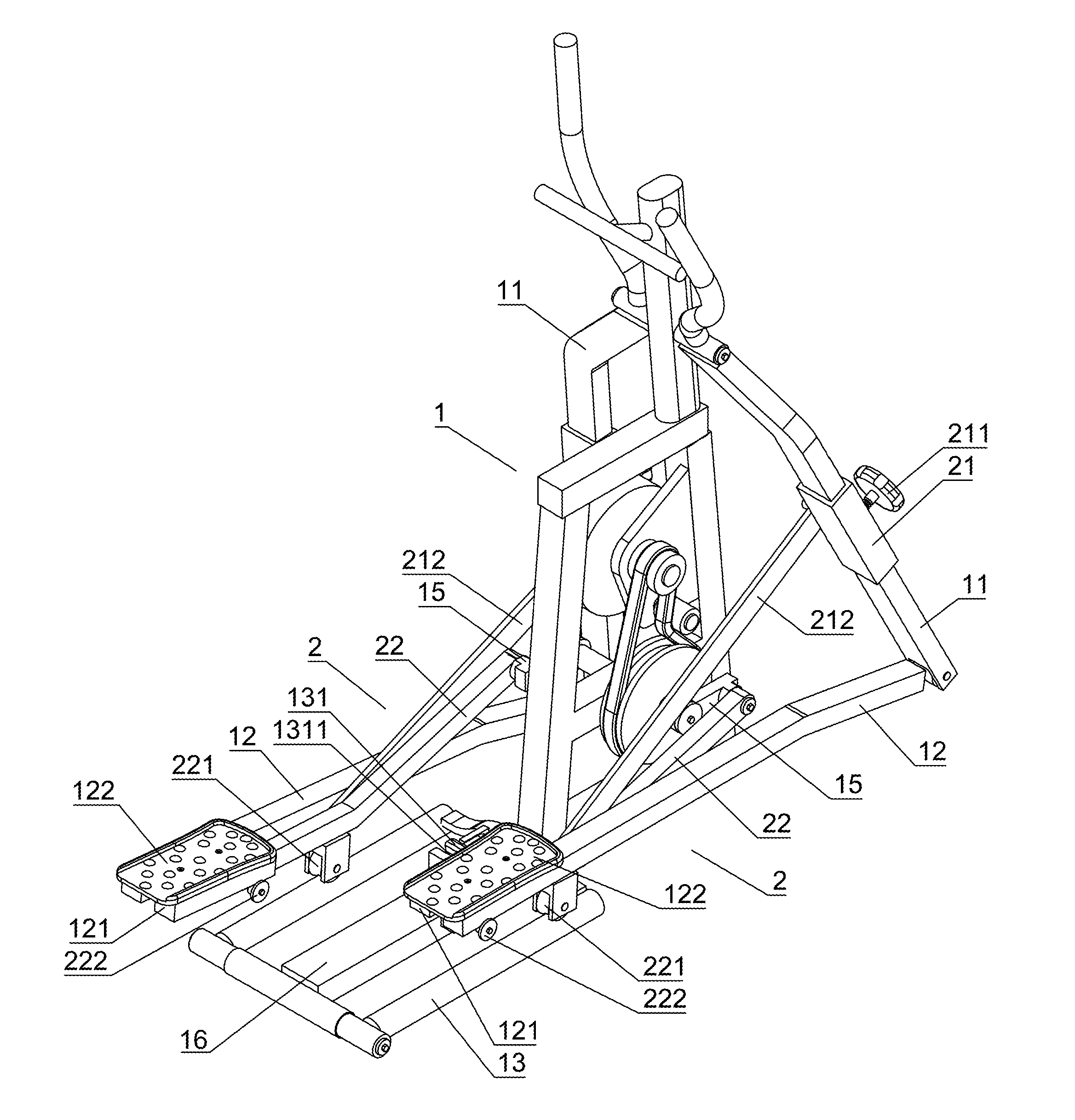
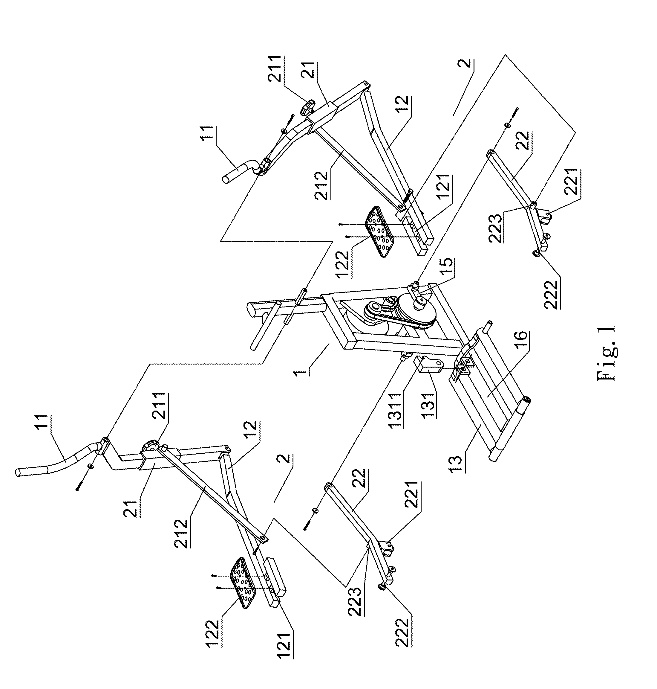
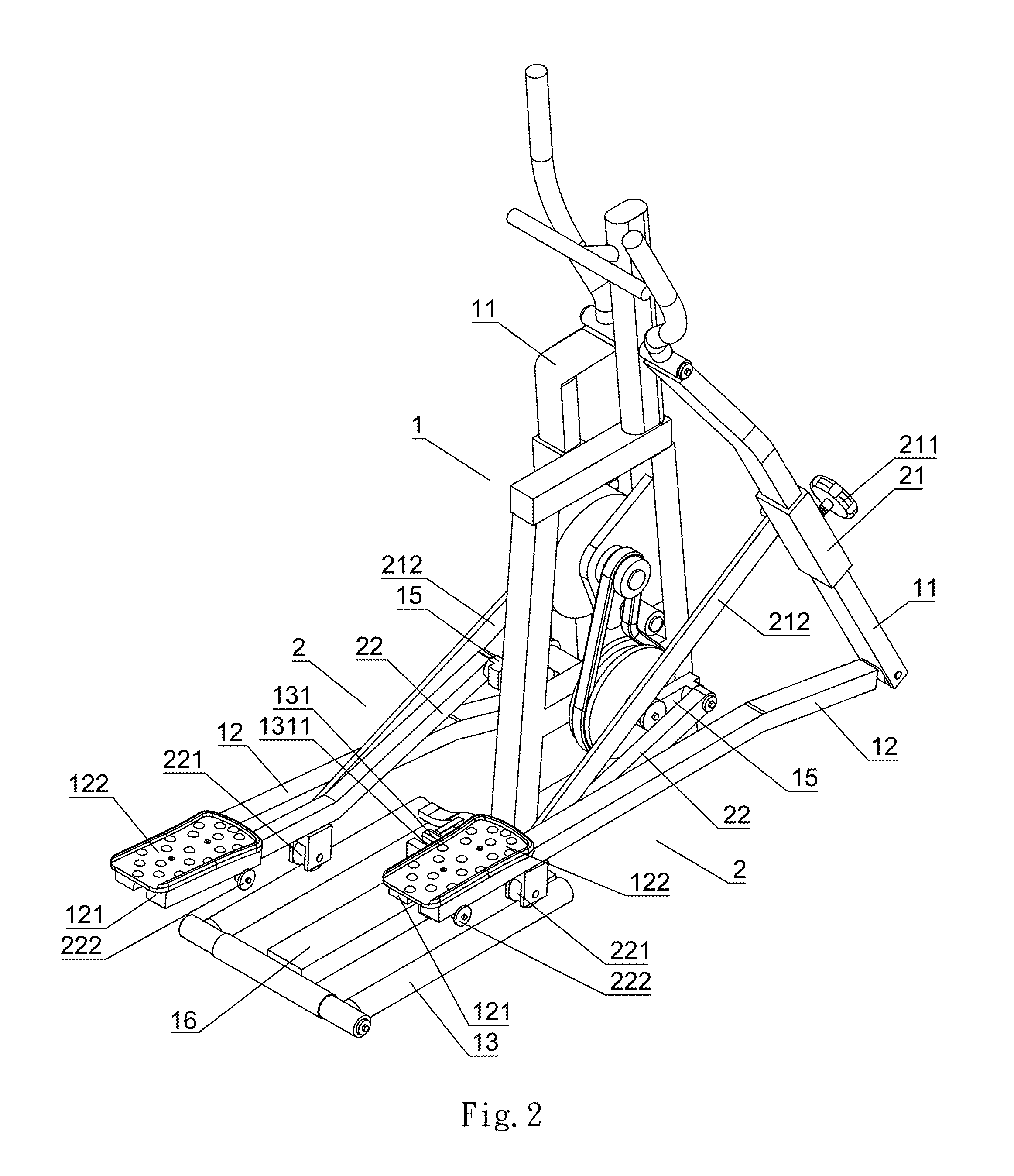
[0025]Referring to FIGS. 1 to 3, an oval transmission structure comprises a platen base 1 and an assistant device 2. The platen base 1 is mainly structured by an oval exercising device. The platen base 1 includes integral swaying moving shafts 11 disposed at two sides thereof for hands to support. Wherein, the swaying moving shaft 11 adopts either an integral shaft or a two-sectional shaft. Lower portions of the swaying moving shaft 11 axially connect to front ends of push-pull shafts 12, respectively. The front portions of the push-pull shafts 12 slope to a predetermined angle, and at rear portions of the push-pull shafts 12 dispose treadle frames 121, which arranges treadles 122 thereon capable of the feet treading. Further, the treadle frames 121 straddle on track wheels 222 of a transmission shaft 22. A track frame 13 is disposed at a rear portion of the oval transmission structure for permitting the sliding wheels 221 of the transmission shaft 22 to slide thereon. Alternatively...


PUM


Abstract

An oval transmission structure utilizes lower ends of swaying moving shafts at two sides thereof to pivot to front ends of push-pull shafts, whose front portions slope to a determined angle. Rear portions of the push-pull shafts offer treadle frames for treadles to dispose with feet. Rear portions of the push-pull shafts further offer a track frame. An assistant device provides a sliding block with a fixing bolt superimposed at a side of the lower portion of the swaying moving shaft. An attached shaft pivoted to a side of the sliding block connects to an axle bolt of a transmission shaft, whose front end axially connects to a crank, whose rear end serially connects to a track wheel and whose middle determined position disposes a sliding wheel thereunder. The reciprocation brought about by the feet, the two cranks axially trigger the front ends of the two transmission shaft for achieving a relative oval action. The axle bolt motivates the attached shaft for driving the sliding block to move the lower portions of the two swaying moving shafts to achieve a relative displacement. Concurrently, the sliding wheel reciprocating flat on the track frame permits upper portions of the swaying moving shafts to sway oppositely. The two treadle frames accordingly slide on the track wheels. A V-shaped leverage of the transmission shaft could attain a favorable transmission effect in time of users operating the back-and-forth reciprocation.

Description

BACKGROUND OF THE INVENTION[0001]1. Field of the Invention[0002]The present invention relates to an oval transmission structure, in particular to a reciprocating movement brought about by both hands and feet, and in particular to an oval transmission structure that could simulate the mounting motion and freely adjust the swaying scope.[0003]2. Description of the Related Art[0004]A general oval exercising device mainly utilizes the hand-controlled swaying moving shafts to axially motivate the push-pull shafts that are disposed by treadles for achieving a back-and-forth movement. Since the other end of the push-pull shaft pivots to a crank, the movement thereof is shown as an oval back-and-forth reciprocation. Thus, the effect of riding a bicycle is also achieved.[0005]However, the existing oval exercising device has the following shortcomings:[0006]1. The existing oval exercising device provides the back-and-forth treading reciprocating movement in accordance with the predetermined o...

Claims


Application Information

Patent Timeline
Patent Type & Authority Patents(United States)
IPC IPC(8): A63B22/00
CPCA63B22/001A63B22/0015A63B22/0664A63B21/225A63B2022/0676
Inventor LAI, YING-CHOU
Owner LAI YING CHOU
Why Eureka
Try Eureka