Optical scanner for image forming apparatus

an image forming apparatus and optical scanner technology, applied in the direction of electrographic process apparatus, printing, instruments, etc., can solve the problems of inability to appropriately control the image write start position on the photosensitive drum, inability to accurately control the image write start position, etc., to prevent thermal deformation of the mirror holding member, prevent excessive increase of the temperature of the mirror holding member, prevent the effect of deviation of the optical path of the light reflected by the mirror

Inactive Publication Date: 2012-07-10
KYOCERA DOCUMENT SOLUTIONS INC
View PDF5 Cites 0 Cited by
  • Summary
  • Abstract
  • Description
  • Claims
  • Application Information

AI Technical Summary

Benefits of technology

[0009]An object of the present invention is to provide an optical scanner for an image forming apparatus, which is capable of preventing functional decline of the device by suppressing optical path deviation.
[0011]According to this configuration, because the mirror holding member for holding the mirror member has the heat radiation part that is exposed to the outside of the housing through the through-hole on the wall surface of the housing, even when the heat generated by the polygon motor raises the temperature of the inside of the housing, and thereby the temperature of the mirror holding member increases, the heat of the mirror holding member is released to the outside of the housing by the heat radiation part that is exposed to the outside of the housing. And, the outside of the housing has a lower temperature than the inside of the housing. Therefore, the excessive increase of the temperature of the mirror holding member is prevented.
[0012]Accordingly, it is possible to prevent thermal deformation of the mirror holding member caused by the increase in the temperature of the mirror holding member, as well as deviation of the position of the mirror member caused by the thermal deformation. Consequently, deviation of the optical path of the light reflected by the mirror member can be prevented. As a result, the reflected light can properly enter the target object, and thereby the optical scanner can be allowed to function normally.

Problems solved by technology

Therefore, when a member holding the mirror is thermally deformed, the optical path of the reflected light moves, which might incapacitates the optical scanner.
For example, when a holding member holding the light guide mirror is thermally deformed and the optical path of the reflected light on the light guide mirror moves, the laser beam might not be able to enter the light receiving element of the base properly, which makes it difficult to appropriately control the image write start position on the photosensitive drum.

Method used


Image

  • Optical scanner for image forming apparatus
  • Optical scanner for image forming apparatus
  • Optical scanner for image forming apparatus

Examples


Embodiment Construction

[0024]An embodiment of the present invention will be described hereinafter with reference to the drawings.

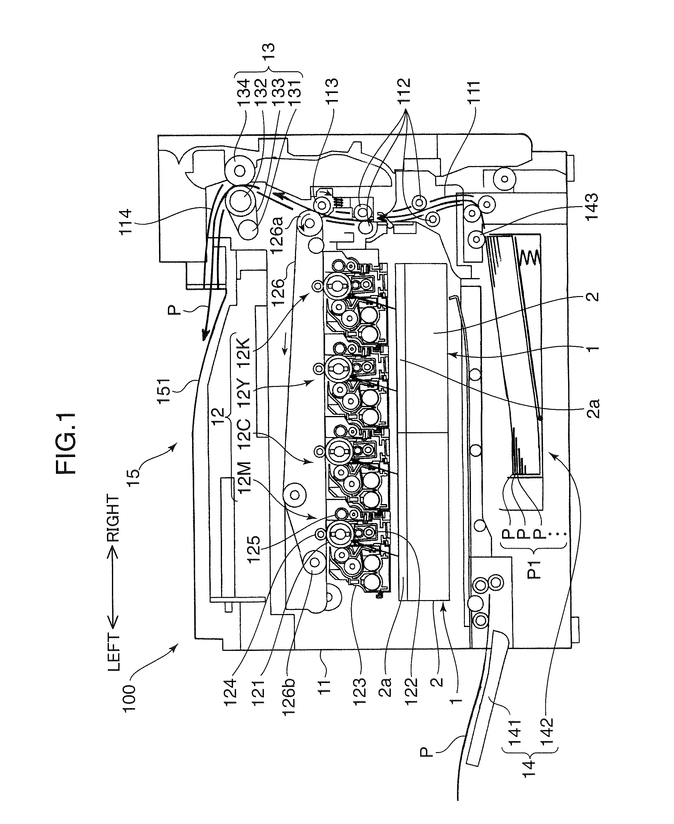
[0025]First, the entire configuration of a printer 100 according to an embodiment of the present invention is described with reference to FIG. 1.

[0026]As shown in FIG. 1, the inside of an apparatus main body 11 of the printer 100 of the present embodiment is provided with an image formation part 12 for forming an image and transferring the image onto a sheet P, a fixing part 13 for performing fixation processing on the image transferred onto the sheet P, and a sheet storage part 14 for storing the sheet P for image formation. The apparatus main body 11 is further provided with a sheet discharge part 15 for discharging the sheet P which the fixation process has been carried out to an upper part of the apparatus main body 11. The printer 100 is configured by these components described above.

[0027]The image formation part 12 forms a toner image on the sheet P supplied by the sheet ...


PUM


Abstract

An optical scanner for an image forming apparatus has a housing having a wall surface provided with a through-hole, and an optical scanning unit, which is provided within the housing, scans light on an object to be scanned in order to form an image on the object to be scanned, and includes: a polygon motor; a polygon mirror that reflects the light while being rotated by a driving force of the polygon motor; a mirror member that reflects the light reflected by the polygon mirror, toward a target object; and a mirror holding member that is attached to the wall surface of the housing and holds the mirror member. The mirror holding member has a heat radiation part that is exposed to the outside of the housing through the through-hole.

Description

BACKGROUND OF THE INVENTION[0001]1. Field of the Invention[0002]The present invention relates to an optical scanner for an image forming apparatus.[0003]2. Description of the Related Art[0004]A conventional image forming apparatus, such as a printer, is provided with an optical scanner (LSU: laser scanner unit) for writing an electrostatic latent image (image) on a photosensitive drum (object to be scanned) (see Japanese Patent Application Publication No. 2002-328321).[0005]Such an optical scanner has, in a housing thereof, a light source for emitting a laser beam, a polygon mirror for reflecting, while rotating, the laser beam emitted from the light source, a polygon motor for rotating and driving the polygon mirror, and an optical system having a lens or a mirror for guiding the laser beam reflected by the polygon mirror onto a photosensitive drum. The laser beam reflected by the polygon mirror is guided onto the photosensitive drum by the optical system and then scans the photose...

Claims


Application Information

Patent Timeline
Patent Type & Authority Patents(United States)
IPC IPC(8): B41J15/14B41J27/00
CPCG02B26/121G03G15/326G03G15/0435
Inventor TOMIOKA, HIROYUKI
Owner KYOCERA DOCUMENT SOLUTIONS INC
Why Eureka
Try Eureka