
Multi-function cutter

a multi-functional, cutter technology, applied in the field of cutters, can solve the problems of inconvenient and dangerous operation of breaking the blade with the blade-breaking device, unintentionally sliding the adjuster to stretch out or retract the blade, and achieving the effect of improving convenience and utility

Inactive Publication Date: 2012-07-17
CHANG CHIH WEI
View PDF15 Cites 26 Cited by
  • Summary
  • Abstract
  • Description
  • Claims
  • Application Information

AI Technical Summary

Benefits of technology

"The present invention provides a multi-function cutter with several technical effects. Firstly, the cutter has a body composed of two halves that can be easily held and exert force through. The blade holder can stretch in multiple stages, ensuring safety and preventing accidental stretching or retracting. Secondly, there is a pivotable spare container for storing at least one spare blade and facilitating replacement of the blade. The blade is formed with at least one dent and a retaining notch, and a positioning member and positioning spring are provided to allow the blade to slide and be positioned along the blade socket. Thirdly, the cutter allows multi-stage adjustment of blade length, replacement of blades and storage of blades, providing improved convenience and utility. Fourthly, the blade has an outer end mounted with a shield so that the point of the blade is shielded from direct exposure, ensuring safe use. Fifthly, the body is composed of the first half and the second half, making it easy to hold and exert force through."

Problems solved by technology

However, since the adjuster itself is raised from the body and tends to be activated when held in a user's palm, the adjuster may be unintentionally slid to stretch out or retract the blade due to excessively exerted cutting force.
This results in either interruption of cutting or broken blade, and the latter can even cause physical danger to the user.
However, the operation of breaking the blade with the blade-breaking device is somehow inconvenient and dangerous.
Moreover, since the blade is attached to the adjuster, it can not be replaced until many components are detached from the body.
Besides, the body lacks for a storage space so spare blades have to be separately stored.
These cause replacement of the blade inconvenient and time-consuming.

Method used


Image

  • Multi-function cutter
  • Multi-function cutter
  • Multi-function cutter

Examples


Embodiment Construction

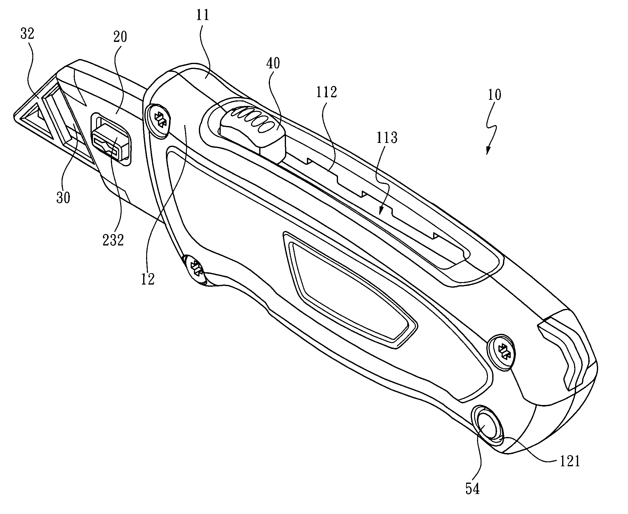
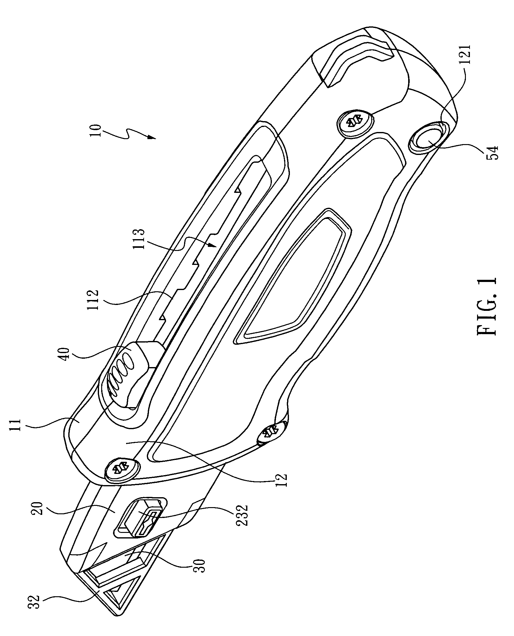
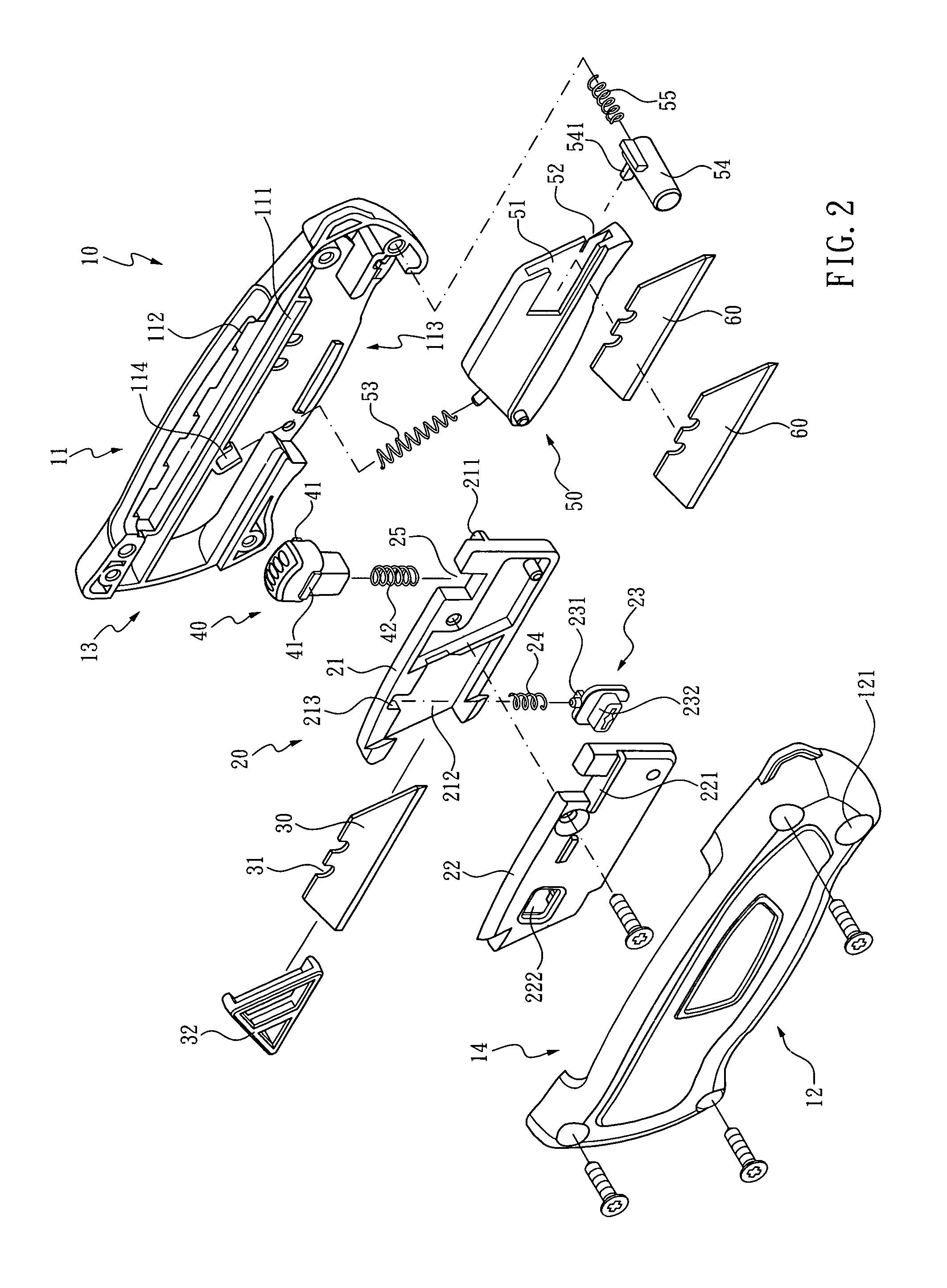
[0024]Referring to FIG. 1 through FIG. 3, the present invention is directed to a multi-function cutter, which primarily comprises a body 10, a blade holder 20, a blade 30, an adjusting device 40, a pivotable spare container 50 and at least one spare blade 60.

[0025]The body 10 is constructed from a first half 11 and a second half 12 that are abreast combined. Therein, each of the first half 11 and the second half 12 has an end edge formed with an indentation 13, an upper edge formed with a concave portion 14, and a guide 111 provided below the concave portion 14. The guides 111 are parallel to the concave portions 14, and two rows of positioning pits 112 are arranged along the concave portions 14, respectively. The first half 11 further has a lower edge formed with an opened section 113 and a receiving seat 114 deposited therein for intercommunicating with the opened section 113. The second half 12 has a through hole 121 formed at a corner thereof.

[0026]The blade holder 20 received i...


PUM


Abstract

A multi-function cutter includes a body composed of a first half and a second half, wherein the first and second halves are formed with indentations, concave portions, guides parallel to the concave portions and rows of positioning pits arranged along the concave portions; a blade holder sliding along the guides to jut out of the indentation and having a spring socket; and an adjusting device deposited in the spring socket and exposing outside the concave portions. Therein, an adjusting spring is arranged between the adjusting device and the spring socket, and the adjusting device is bilaterally formed with wedge portions for detachably engaging the corresponding positioning pits, so as to stretch the blade holder in multiple stages.

Description

BACKGROUND OF THE INVENTION[0001]1. Technical Field[0002]The present invention relates to cutters, and more particularly, to a multi-function cutter that allows multi-stage adjustment of blade length, replacement of blades and storage of blades.[0003]2. Description of Related Art[0004]In industrial practice and people daily life, utility knifes are popular and essential. A conventional utility knife typically has its body mounted with a sliding adjuster where a blade is fixed, so that when the sliding adjuster is operated, the blade juts out of or retracts into the body. In addition, on the body, there is a row of sawteeth arranged along the sliding direction of the sliding adjuster for a retaining portion of the sliding adjuster to detachably couple. Thereby, the length of the blade exposed outside the body can be adjusted for meeting cutting needs, and then the blade can be positioned with the retaining portion wedged between two positionally-corresponding adjacent sawteeth.[0005]...

Claims


Application Information

Patent Timeline
Patent Type & Authority Patents(United States)
IPC IPC(8): B26B1/08
CPCB26B5/001B26B29/02
Inventor CHANG, CHIH-WEI
Owner CHANG CHIH WEI
Learn More