
Support assembly

a technology for supporting items and objects, applied in the direction of lighting support devices, candle holders, incandescent lamp details, etc., can solve the problems of limited use, easy to snag clothing or other objects on the hooks, and limited suppor

Inactive Publication Date: 2012-07-24
HIDDENHOOK
View PDF21 Cites 2 Cited by
  • Summary
  • Abstract
  • Description
  • Claims
  • Application Information

AI Technical Summary

Benefits of technology

The assembly provides stable and adjustable support for diverse items, preventing snagging and accommodating different orientations, while allowing for easy item interchange and electrical supply when needed.

Problems solved by technology

An issue with conventional hooks is that they generally project outwardly from the second wall, meaning it is easy to snag clothing or other objects on the hooks.
Depending on the positioning of the hook, it is possible for a passer-by to impact against the hook, causing injury.
A further issue is that the hooks may only provide limited support, and they only support items correctly in one orientation of the hook.
That makes conventional hooks of limited use for some purposes in undulating environments such as on boats, aircraft, or in automobiles.
While those devices are designed so that the hooks do not project to address the snagging issue, they only provide a limited amount of support in undulating environments.
Those devices would only function correctly on certain orientations.
Further, those devices are only useful for supporting plastic shopping bags or similar items.

Method used


Image

  • Support assembly
  • Support assembly
  • Support assembly

Examples


Embodiment Construction

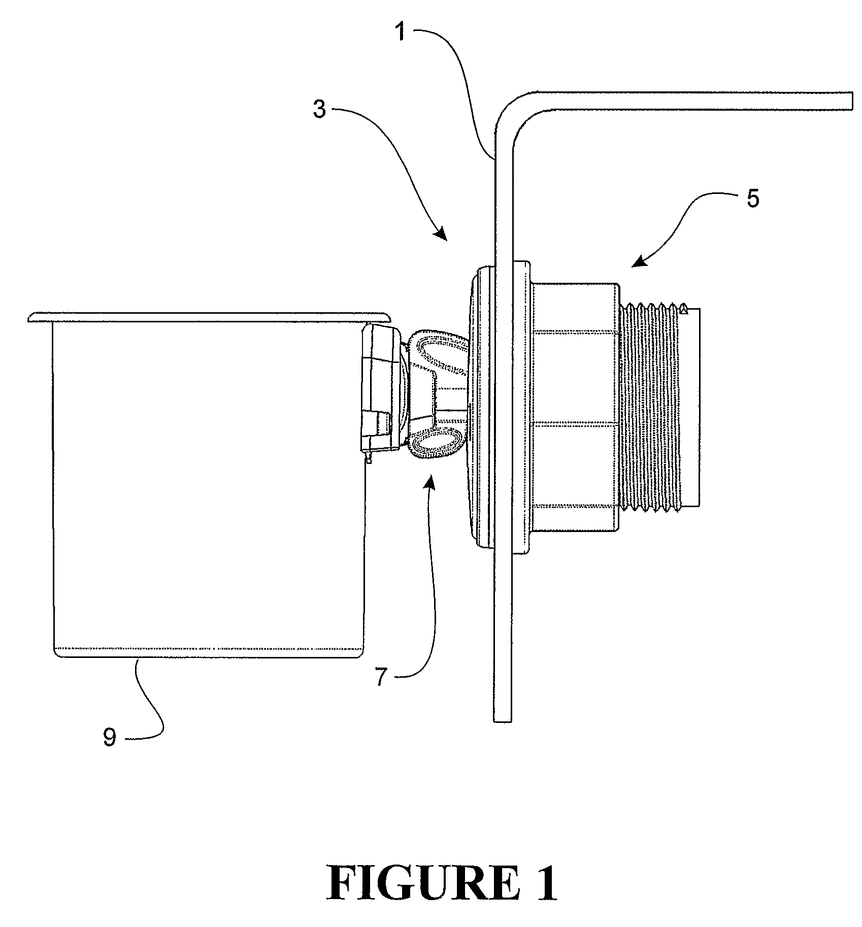
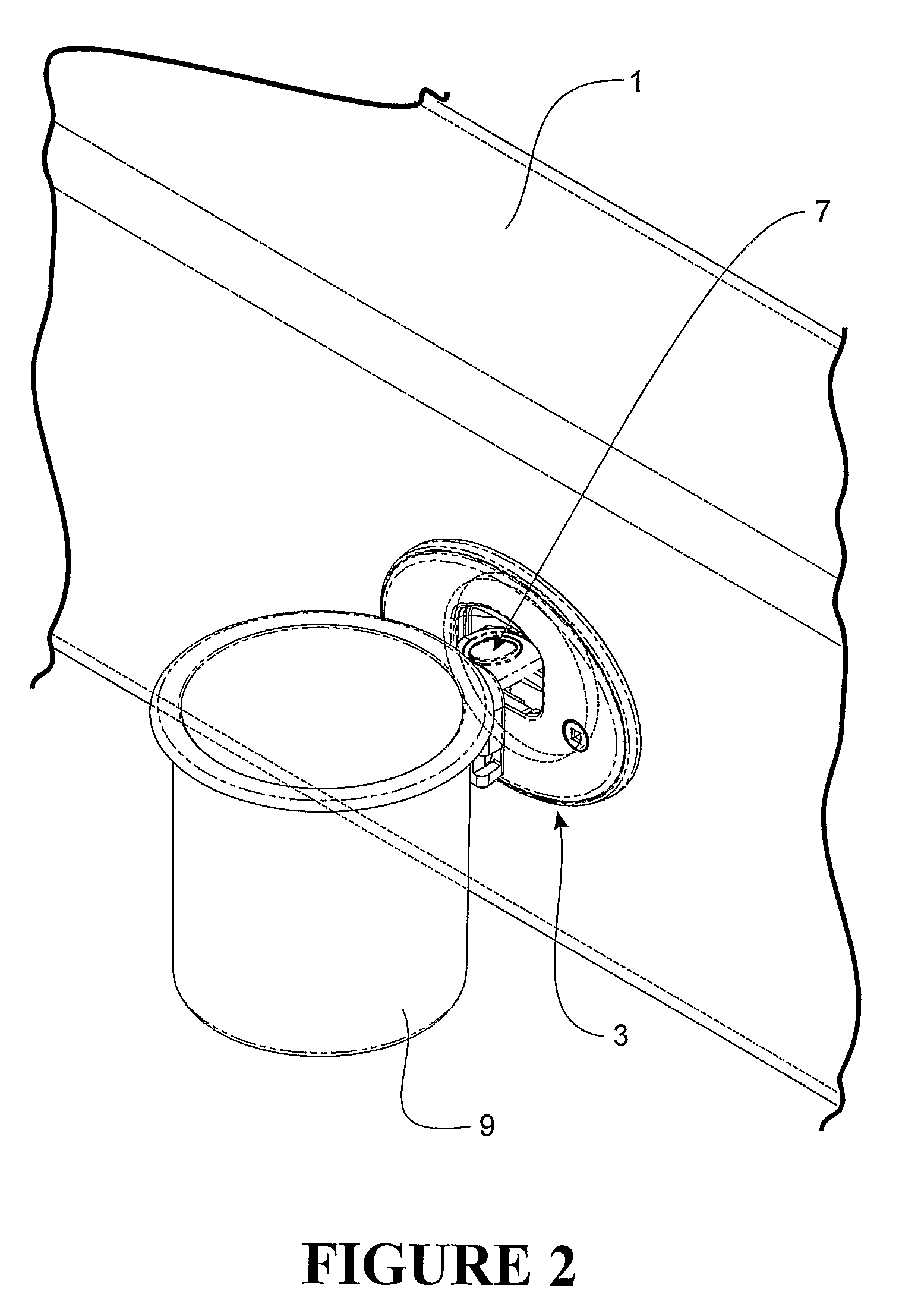
[0092]Referring to FIGS. 1 to 3, a preferred embodiment support assembly 3 is shown attached to a panel 1 such as a fibreglass wall panel of a boat for example.

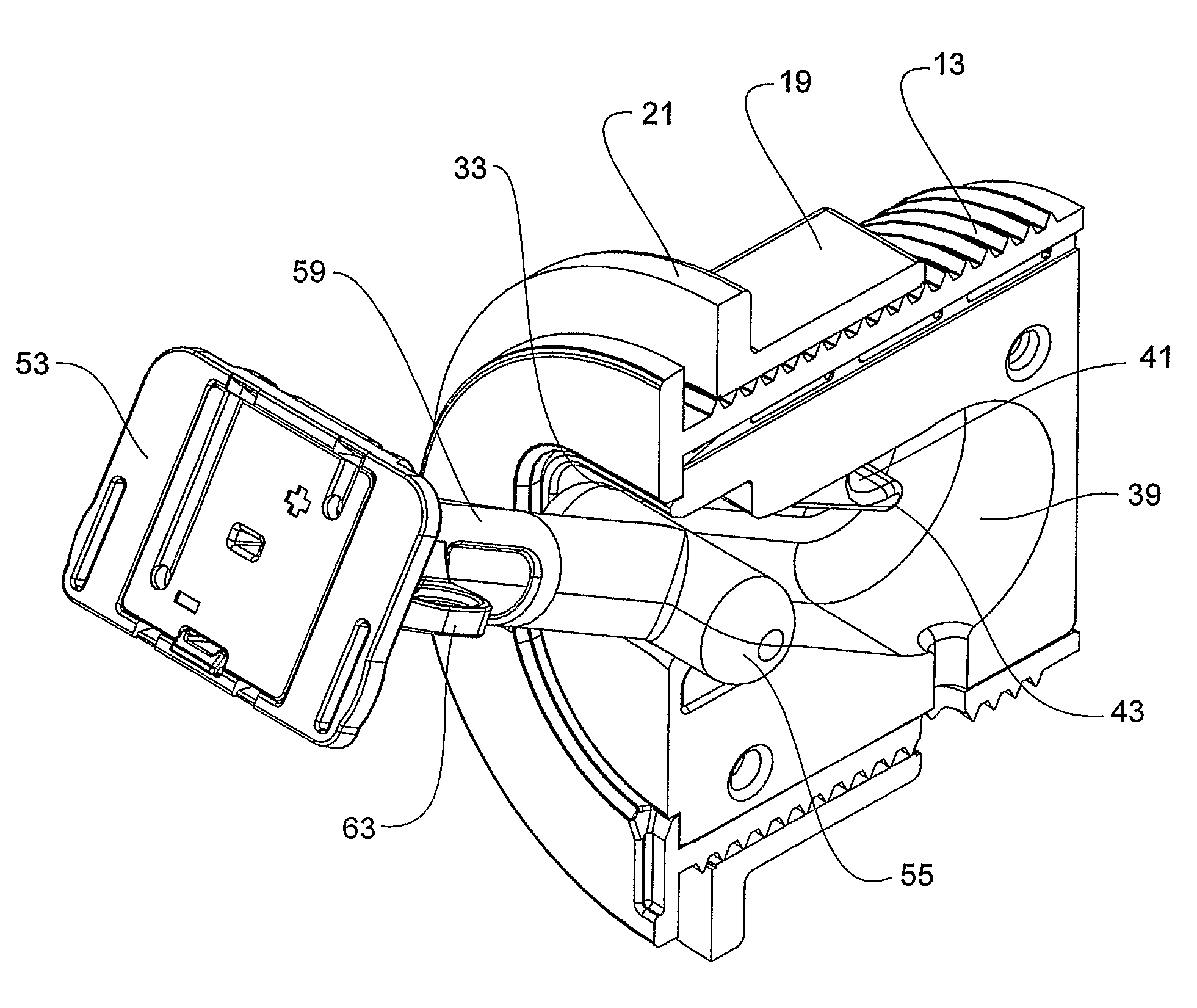
[0093]The preferred embodiment support assembly 3 comprises a base unit 5 which is attachable to the panel 1, and a support component 7 which is engageable with the base unit 5 and is arranged to support an item 9 from the base unit, and thereby from the panel 1. In the embodiment shown, the item being supported is a mug or cup 9. However, the support component may be configured to support a number of different items as outlined below.

[0094]Referring now to FIGS. 4 to 9, the base unit comprises a housing 11. As can be seen from FIGS. 6 and 7, the housing 11 preferably comprises two housing portions 11a, 11b. The housing portions 11a, 11b may be fully separable, or could be hinged to one another as shown, such as via a hinge 11c. In the embodiment shown, the housing 11 is in the form of an insert which is receivable in a surro...


PUM


Abstract

An assembly for supporting an item has a housing (11) has a first surface (23), a second surface (25) opposite to the first surface, and a periphery (27) between the first and second surface. An opening (33) is provided in the first surface of the housing and a cavity (35) extends inwardly from the opening. At least one engagement surface (43) is present in the cavity and positioned toward the second surface, and configured to provide a first region of support. A support component (7) for supporting the item is configured to engage with the engagement surface(s) (43) of the housing with a portion of the support component extending from the opening (33) of the housing and supported by a second region of support at or toward the fkst surface of the housing, to support the item. A base unit and support component are also provided.

Description

CROSS REFERENCE TO RELATED APPLICATION[0001]This application claims the benefit of U.S. Provisional Application No. 60 / 736,206, filed Nov. 14, 2005, the entirety of which is incorporated herein by reference.FIELD OF THE INVENTION[0002]The present invention relates to an assembly for supporting an item. More particularly, although not exclusively, the assembly may be suitable for supporting an item from a wall panel, ceiling panel, or the like.BACKGROUND OF THE INVENTION[0003]In many applications, it is desirable to support or hang a first item such as an item of clothing from a wall panel or the like. For that purpose, a hook or the like is attached to the wall panel, and the item of clothing can be hung from the hook. An issue with conventional hooks is that they generally project outwardly from the second wall, meaning it is easy to snag clothing or other objects on the hooks. Depending on the positioning of the hook, it is possible for a passer-by to impact against the hook, caus...

Claims


Application Information

Patent Timeline
Patent Type & Authority Patents(United States)
IPC IPC(8): A47G29/00
CPCB60N3/103F16B5/0685F16B45/00B60R2011/0061Y10T403/7015B60R2011/0078A47G29/00
Inventor MARSHALL, PETER ANTHONY
Owner HIDDENHOOK
Learn More