Power supplying system for a sliding structure

a technology for sliding structures and power supply systems, applied in the direction of insulated conductors, cables, coupling device connections, etc., can solve the problems of high component cost and assembly cos

Active Publication Date: 2012-07-24
YAZAKI CORP +1
View PDF10 Cites 14 Cited by
  • Summary
  • Abstract
  • Description
  • Claims
  • Application Information

AI Technical Summary

Problems solved by technology

Therefore, there is a problem that a component cost and an assembling cost are expensive.
This problem is applied to not only a sliding door of a vehicle, but also a siding door or the like of the other machine.

Method used


Image

  • Power supplying system for a sliding structure
  • Power supplying system for a sliding structure
  • Power supplying system for a sliding structure

Examples


Embodiment Construction

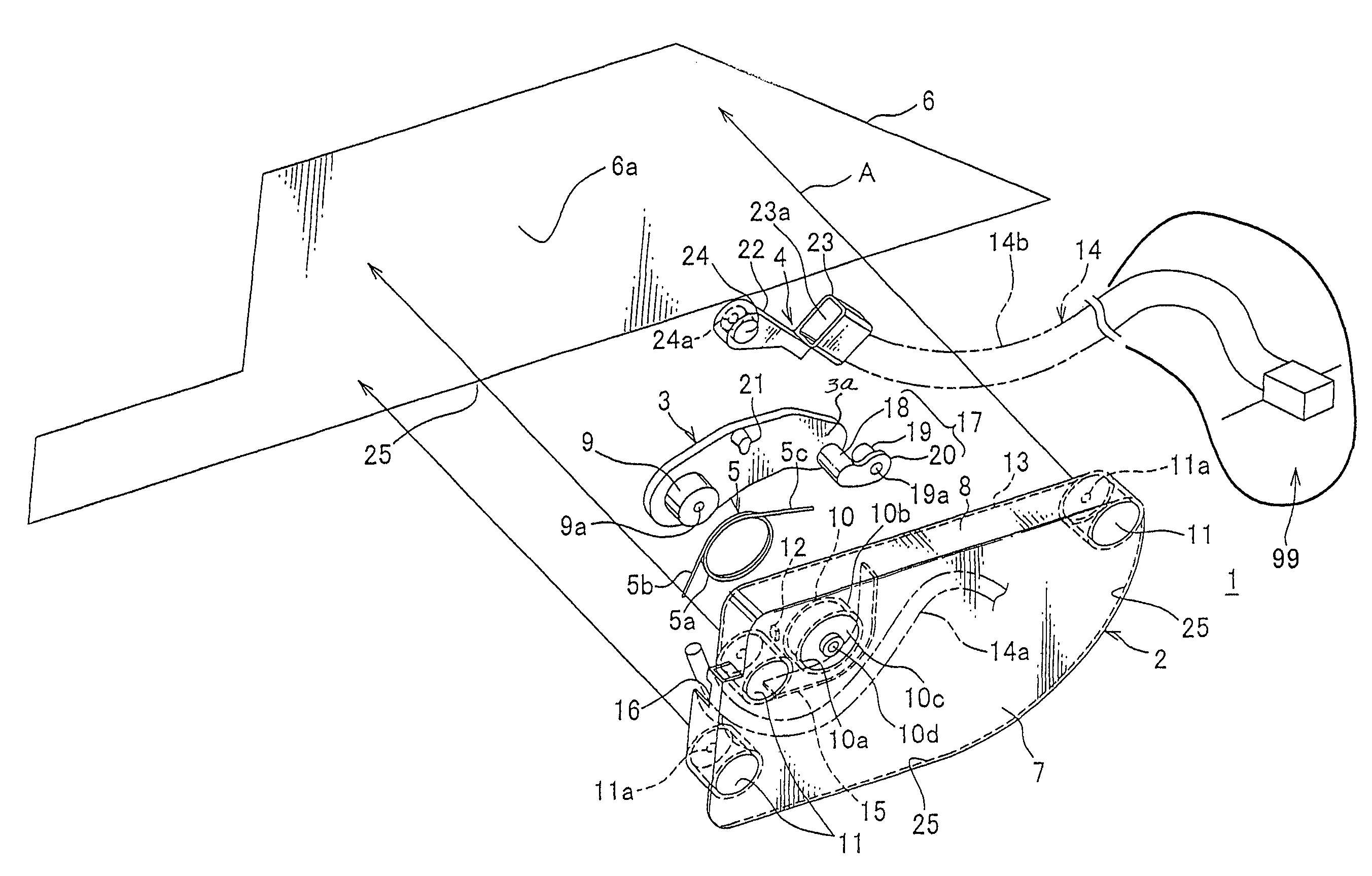
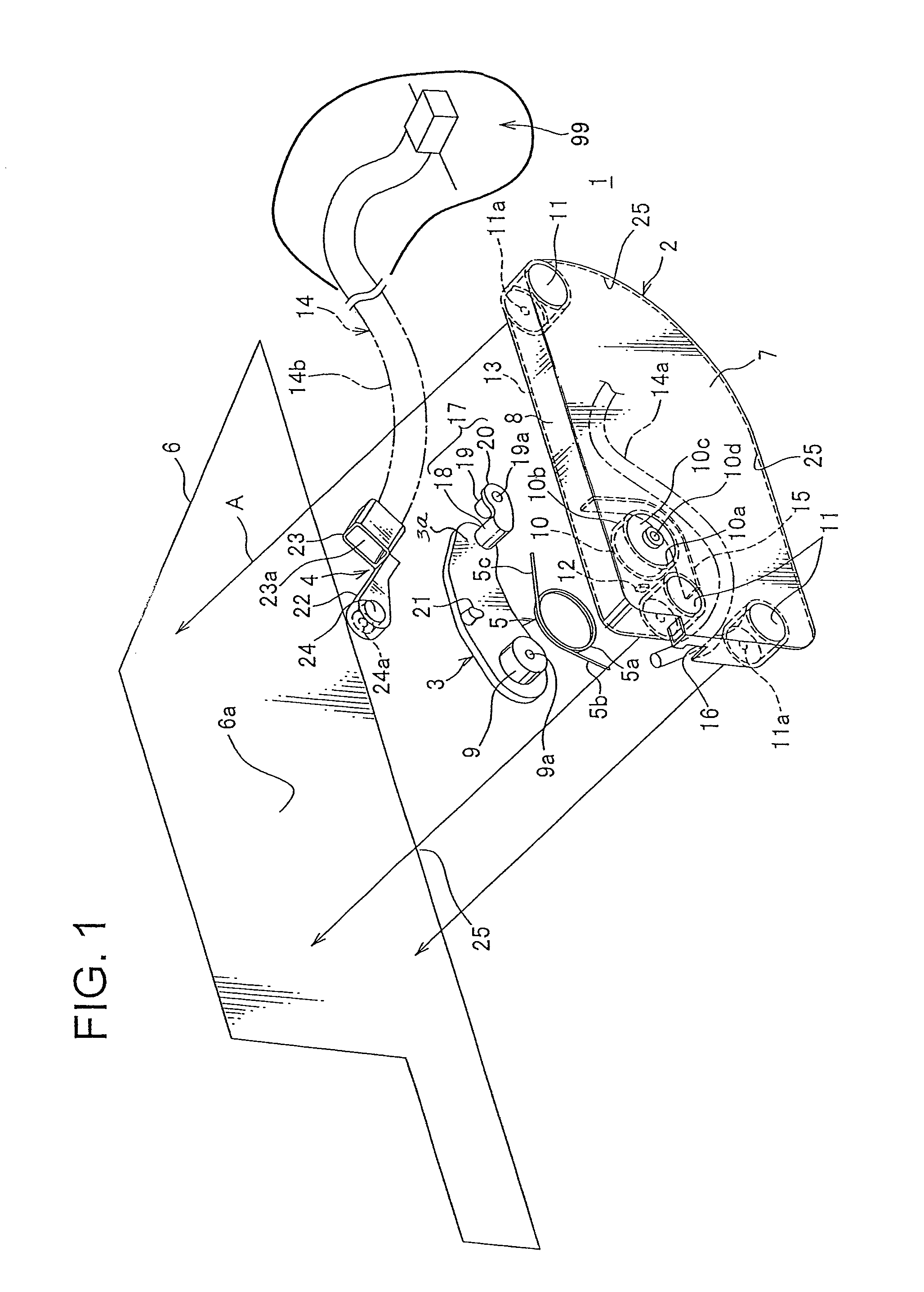
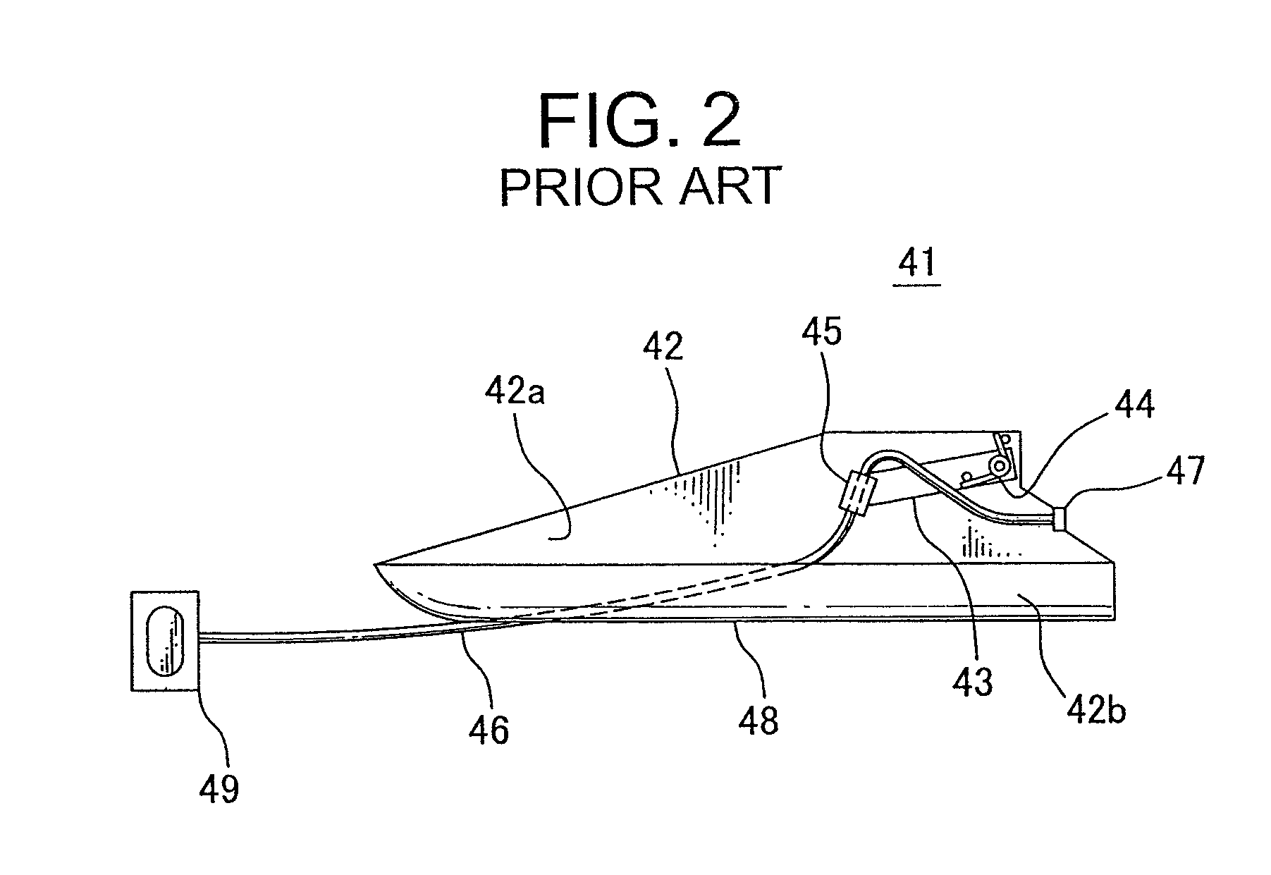
[0025]FIG. 1 shows a first embodiment of a power-supplying system for a sliding structure according to the present invention. In FIG. 1, the power-supplying system for a right side sliding door of a vehicle is shown (FIG. 3 shows a conventional power-supplying system for a left side sliding door).

[0026]This power-supplying system 1 includes: a synthetic resin-made protector cover 2; a synthetic resin-made or metallic link arm 3 rotatably supported by the protector cover 2; a synthetic resin-made harness holding member 4 rotatably provided at a tip end of the link arm 3; and a metallic torsion coil spring (elastic member) 5 urging the link arm 3 in a harness slack absorbing direction (upward).

[0027]The protector is composed of only the protector cover 2, and the protector base shown in FIG. 3 is omitted. Further, a door inner panel (panel) 6 is made of synthetic resin, and the protector cover 2 is fixed to the synthetic resin-made door inner panel 6 with tapping screws (not shown).

[0...


PUM


Abstract

A power-supplying system for a sliding structure includes: a protector cover having a base plate and a flange-shaped peripheral wall; a link arm rotatably supported along the base plate in the protector cover, and supporting a wiring harness at a top end side of a rotation; and an elastic member urging the link arm in a harness slack absorbing direction. The power-supplying system is disposed in the sliding structure. The protector cover is fixed to a panel of the sliding structure. An opening of the protector cover facing the base plate at a rear side is covered by the panel. The wiring harness is guided out from an oblong opening interposed between the protector cover and the panel toward a fixing structure.

Description

CROSS REFERENCE TO RELATED APPLICATIONS[0001]This application is on the basis of Japanese Patent Application No. 2009-081197, the contents of which are hereby incorporated by reference.BACKGROUND OF THE INVENTION[0002]1. Field of the Invention[0003]The present invention relates to a power-supplying system for a sliding structure for continuously supplying electric power to such as a sliding door of a vehicle with a wiring harness.[0004]2. Description of the Related Art[0005]FIG. 2 shows an embodiment of a conventional power-supplying system for a sliding structure (See Patent Document 1).[0006]In this power-supplying system 41, a link arm 43 is pivotally supported in a synthetic resin made protector 42 in a substantially trapezoidal shape at a sliding door side of a vehicle, and a metallic torsion coil spring 44 is attached to a shaft 50 of the link arm 43. The link arm 43 is urged upward by the coil spring 44. A harness holder 45 is provided at a tip end of the link arm 43. The wir...

Claims


Application Information

Patent Timeline
Patent Type & Authority Patents(United States)
IPC IPC(8): H02G3/04
CPCB60R16/027H02G11/003
Inventor KATOU, MITSUNOBUNISHIMURA, TOMOAKIINAGAKI, MOTONARI
Owner YAZAKI CORP
Why Eureka
Try Eureka