Cage trap with easy set and release mechanism

a cage trap and release mechanism technology, applied in the field of cage traps, can solve the problems of the door closing trigger or actuation mechanism, the difficulty of keeping the cage trap door closed, and the trap relying on the cable mechanism, so as to achieve the effect of safe and easy release, safe and easy setting, and safe and easy releas

Active Publication Date: 2012-07-31
WOODSTREAM CORP
View PDF24 Cites 18 Cited by
  • Summary
  • Abstract
  • Description
  • Claims
  • Application Information

AI Technical Summary

Benefits of technology

[0011]The trip mechanism is in the form of a pedal movably mounted in the animal enclosure with a trigger rod secured to the pedal and to the latch mechanism. When an animal enters the animal enclosure, the weight of the animal moves the pedal from a first raised position to a second lowered position for causing the trigger rod to move the latch mechanism thereby releasing the hand grip. Releasing the hand grip results in release of the tension on the actuating member and movement of the hand grip from its second position to its first position. The weight of the door moves the door from the opened position to the closed position thereby trapping the animal in the animal enclosure.
[0020]Additional objects of the invention include, for example, the provision of a cage trap which is durable, reliable and user friendly, which is animal friendly and which traps the animal safely in a humane manner, and which can be manufactured from readily available components and in a cost-effective manner.

Problems solved by technology

Another problem with the prior art cage traps is the trigger or actuation mechanism used to initiate the door closure.
Prior art cage traps relying on cable mechanisms also present difficulties associated with keeping the cage trap door closed once an animal is inside.

Method used


Image

  • Cage trap with easy set and release mechanism
  • Cage trap with easy set and release mechanism
  • Cage trap with easy set and release mechanism

Examples


Embodiment Construction

[0057]In describing preferred embodiments of the present invention illustrated in the drawings, specific terminology is employed for the sake of clarity. However, the invention is not intended to be limited to the specific terminology so selected, and it is to be understood that each specific element includes all technical equivalents that operate in a similar manner to accomplish a similar purpose.

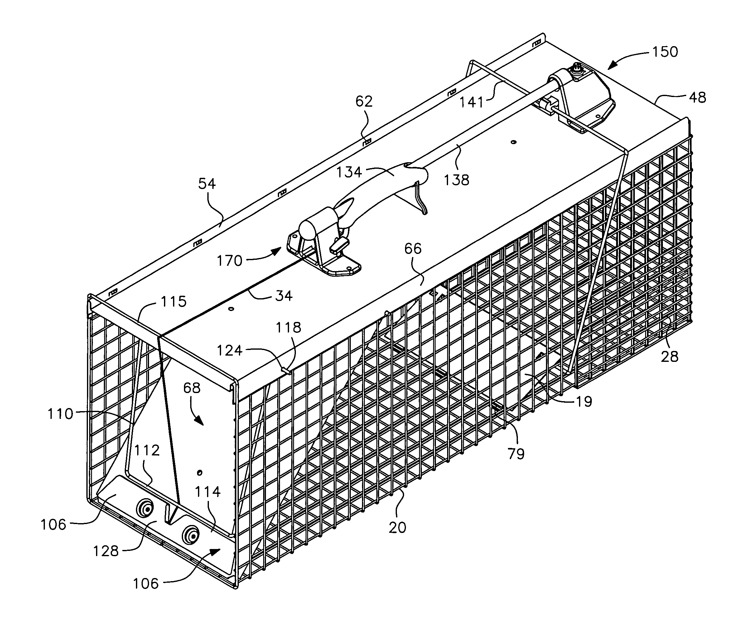
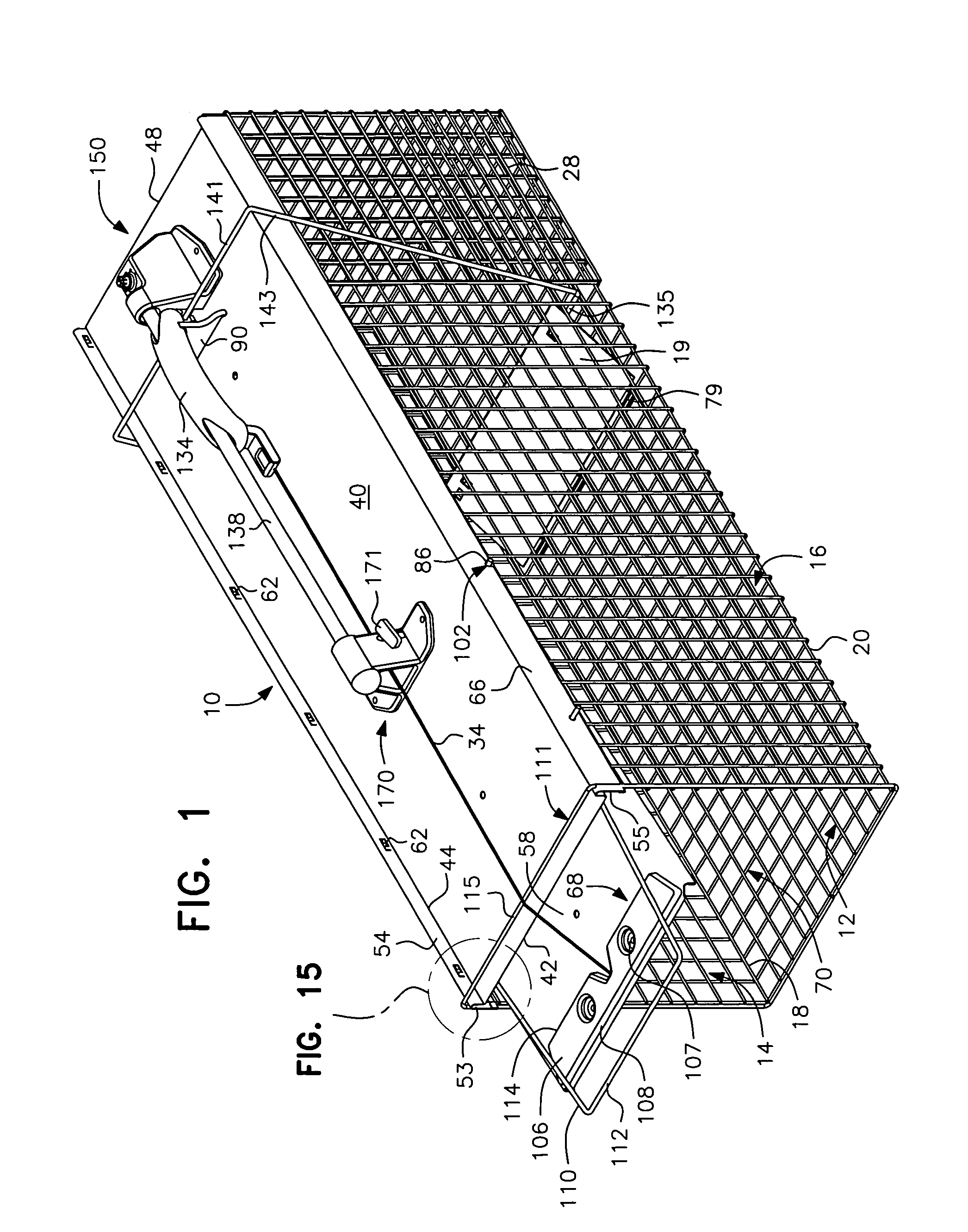
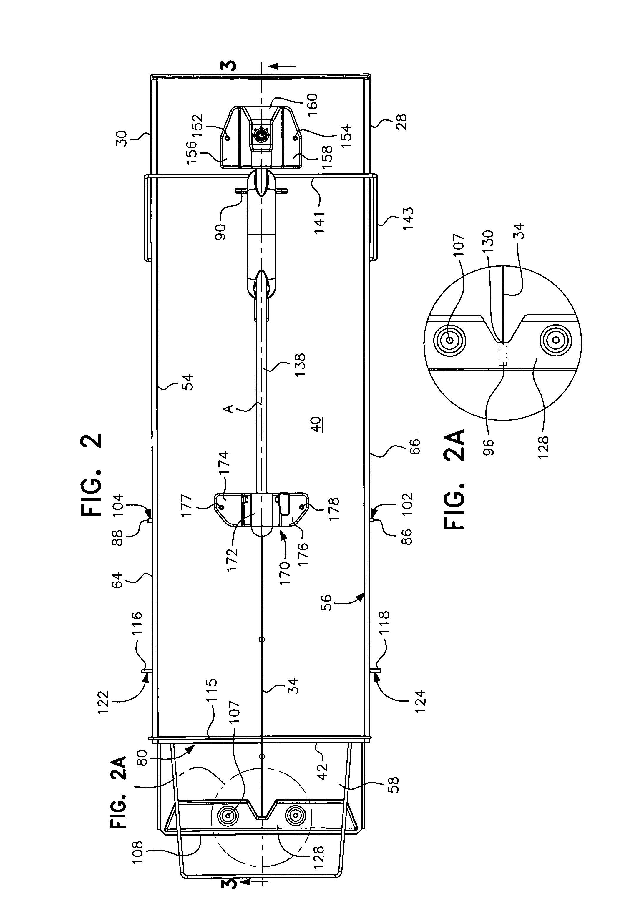
[0058]With reference to FIGS. 1 to 3, 7 and 8, the cage trap of the present invention is generally designated by reference numeral 10. Trap 10 includes a box-like cage having an elongated base 12 and opposed sidewalls 14 and 16 preferably formed and folded from a single piece of wire mesh. The sidewalls emanate from the longitudinal edges 18 and 20 of the base 12 in an upward direction. The walls 14 and 16 define planes that are essentially parallel to each other.

[0059]As seen particularly in FIGS. 1 and 3, in the preferred form of the invention, the base 12 and side walls 14, 16 include ...


PUM


Abstract

A cage type animal trap having an enclosure with an animal access opening into a vacant interior sized to receive an animal to be trapped. The access opening is closed by a door that is movable from a closed to an opened position by an actuating mechanism having a flexible actuating member with one end secured to the door and the other end releasably held by a latch mechanism. The latch mechanism is configured to move the door to the opened position by tensioning the actuating member and, in response to a trigger mechanism, to release the second end of the actuating member and allow the door to move from the opened position to the closed position thereby trapping the animal in the animal enclosure. A door lock in abutment with the outer surface of the door prevents the door from being opened by a trapped animal. A part of the actuating mechanism is in engagement with the door lock when the door is closed such that the door lock is automatically disengaged when the actuating member is tensioned.

Description

[0001]This application is entitled to and hereby claims the priority of co-pending U.S. application Ser. No. 11 / 097,195 filed Apr. 4, 2005, and co-pending U.S. application Ser. No. 11 / 600,085 filed Nov. 16, 2006.BACKGROUND OF THE INVENTION[0002]1. Field of the Invention[0003]This invention relates to cage-type animal traps of the kind generally used outdoors for trapping small to medium sized animals without harming the trapped animal. Such traps commonly comprise a cage of metal wire mesh or the like with a door held open by a trigger mechanism until an animal is lured into the trap by suitable pre-inserted bait. After the animal enters the interior of the trap, the animal's weight pressed against the trigger actuates a trip which releases and closes the door, thereby trapping the animal inside the cage.[0004]2. Description of the Prior Art[0005]Cage traps of the prior art have specific setting and releasing mechanisms which typically consist of a pan, a trigger rod, a latching dev...

Claims


Application Information

Patent Timeline
Patent Type & Authority Patents(United States)
IPC IPC(8): A01M1/10A01M23/00
CPCA01M23/18A01M23/24
Inventor RICH, CHRISTOPHER TCRUZ, ROBERT T.HOLLIDAY, EDWARD J.LUBIC, MARKO
Owner WOODSTREAM CORP
Why Eureka
Try Eureka