Oilfield elements having controlled solubility and methods of use

a technology of oilfield elements and solubility, applied in the field of oilfield exploration, production and testing, can solve the problems of disincentive to their use, inability to always consider their strength and durability, and inability to dissolve and/or degrade in a shorter time period than the desired or anticipated by well operating personnel, and achieve the effect of easing the element traversing

Active Publication Date: 2012-07-31
SCHLUMBERGER TECH CORP
View PDF100 Cites 186 Cited by
  • Summary
  • Abstract
  • Description
  • Claims
  • Application Information

AI Technical Summary

Benefits of technology

[0016]Oilfield elements of the invention may have a number of shapes, as long as the element is able to perform its intended function when not exposed to aqueous conditions, for example traverse at least a portion of a wellbore and block off a perforation, or a portion of a wellbore as a wellbore plug, or to actuate (open or close) a downhole valve. Suitable well operating oilfield element shapes include cylindrical, round, bar shapes, dart shapes and the like. A dart shape means that the bottom has a tapered end, in some cases pointed. Well operating oilfield elements of the invention will generally have first and second ends that may be tapered in shape to contribute to the ease of the element traversing through a wellbore.

Problems solved by technology

If they are not degradable in the wellbore environment, there is a disincentive to their use.
Dissolvable diverter balls are known in diversion operations, however, during use their strength and durability is not always considered.
However, if these non-dissolvable fracturing elements are composed of non-engineered materials, they may dissolve and / or degrade in a shorter time period than desired or anticipated by the well operating personnel.
The main drawback of these materials listed is that they do not dissolve rapidly enough.

Method used


Image

  • Oilfield elements having controlled solubility and methods of use
  • Oilfield elements having controlled solubility and methods of use
  • Oilfield elements having controlled solubility and methods of use

Examples


embodiment 70

[0085]FIGS. 5A and 5B illustrate two schematic perspective views of another well operating element embodiment 70 of the invention. These figures illustrate a collet 72 of first, relatively insoluble component having a plurality of supports arms 74 extending therefrom, which serve to support and hold portions 76 of second, relatively water-soluble component 47 in place until they are dissolved. Embodiment 70 may also include one or more exposure holes 16 in the second component, although this is optional.

embodiment 50

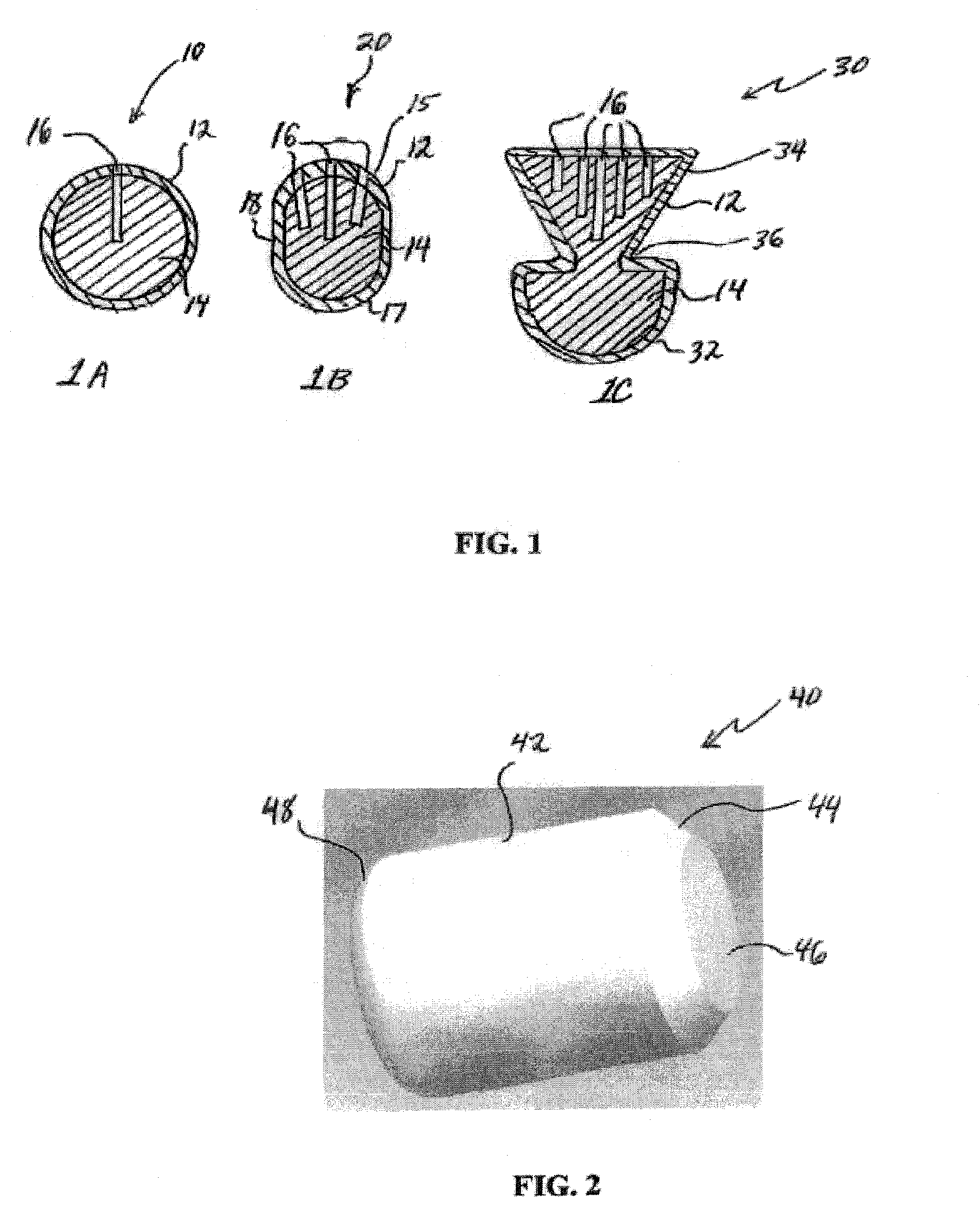
[0086]FIG. 6 is a perspective view of another well operating element embodiment 80 of the invention, which is similar to embodiment 50 of FIG. 3, except that more of the second relatively water-soluble component 47 is exposed, illustrating one of many mechanisms of controlling the dissolvability of the second material. First component 44 and 46 may be a hollow cap, or it may be a placed directly in contact with second component. In other words, second component 47 may have a conical section and flat end corresponding substantially with conical section 44 and flat end 46 of the first component.

[0087]FIGS. 7A, 7B, and 8 illustrate cross-sectional views of three more embodiments 90, 95, and 100, respectively, of well operating elements of the invention, all three embodiments being elongated balls, but these embodiments are merely exemplary. Embodiment 90 of FIG. 7A illustrates are large portion 14 of second component, and an embedded, conical first component 91 having interfaces 92 and...


PUM

PropertyMeasurementUnit
tensile strengthaaaaaaaaaa

Abstract

Oilfield elements are described, one embodiment comprising a combination of a normally insoluble metal with an element selected from a second metal, a semi-metallic material, and non-metallic materials; and one or more solubility-modified high strength and / or high-toughness polymeric materials selected from polyamides, polyethers, and liquid crystal polymers. Methods of using the oilfield elements in oilfield operations are also described. This abstract allows a searcher or other reader to quickly ascertain the subject matter of the disclosure. It will not be used to interpret or limit the scope or meaning of the claims.

Description

CROSS-REFERENCE TO RELATED APPLICATIONS[0001]The present application claims priority under 35 U.S.C. §119(e) to U.S. Provisional Application Ser. No. 60 / 737,439, filed Nov. 16, 2005, incorporated by reference herein in its entirety.BACKGROUND OF THE INVENTION[0002]1. Field of Invention[0003]The present invention relates generally to the field of oilfield exploration, production, and testing, and more specifically to a material and soluble oilfield elements such as well operating elements and methods of using same, which exhibit a combination of rapid solubility and high strength and / or high toughness. This invention also relates to and altering the solubility of above mentioned high strength soluble oilfield elements and well operating elements.[0004]2. Related Art[0005]A diverter ball is a ball that is dropped or pumped through wellbore tubulars in a process known as diversion, and used during acidizing and fracturing operations. One common method of fracturing wells is to have a m...

Claims


Application Information

Patent Timeline
Patent Type & Authority Patents(United States)
IPC IPC(8): B29D22/00E21B29/00E21B33/12
CPCE21B34/14Y10T428/13C09K8/80E21B43/267E21B34/142
Inventor VAIDYA, NITIN Y.BHAVSAR, RASHMIMARYA, MANUEL
Owner SCHLUMBERGER TECH CORP
Why Eureka
Try Eureka