Vehicular lamp

a technology for lamps and vehicles, applied in the field of lamps for vehicles, can solve the problems of increasing the number of parts, increasing the cost, and limited vehicle types, and achieve the effects of reducing the number of parts that need to be managed, reducing the cost, and facilitating the management of parts

Inactive Publication Date: 2012-08-07
KOITO MFG CO LTD
View PDF9 Cites 0 Cited by
  • Summary
  • Abstract
  • Description
  • Claims
  • Application Information

AI Technical Summary

Benefits of technology

[0014](Operation) The manufacturing costs of the lamp body can be reduced by integrating the optical axis adjusting portions and further simplifying the shape of the lamp body.
[0019]According to the vehicular lamp according to one or more embodiments, the shape of the lamp body is made common between an external attachment type of vehicle and an internal attachment type of vehicle. As a result, the mold can be shared and the number of parts that need to be managed decreases, so the cost can be reduced and part management is easier.
[0020]According to the vehicular lamp according to one or more embodiments, a lamp body (a lamp unit) that can be attached to the vehicle body from the outside of the vehicle body via the first vertical tilt axis structural members can be attached to the vehicle body also from the inside of the vehicle body via the bracket and the second vertical tilt axis structural members, and the mold of the lamp body can be shared, so manufacturing costs of the vehicular lamp can be reduced.
[0021]According to one or more embodiments, manufacturing costs of the lamp body that include the mold-making cost can be reduced by simplifying the lamp body shape.

Problems solved by technology

Regarding this, the lamp unit in Patent Document 1 is unable to be attached directly to the vehicle body from the front of the vehicle body without a bracket, so the type of vehicle to which it can be employed is limited.
This increased costs due to an increase in the number of parts and the need to prepare separate molds, as well as led to an increase in the complexity of management due to the increase in the number of parts.

Method used


Image

  • Vehicular lamp
  • Vehicular lamp
  • Vehicular lamp

Examples


Embodiment Construction

[0032]Next, embodiments of the present invention will be described with reference to FIG. 1A to FIG. 6.

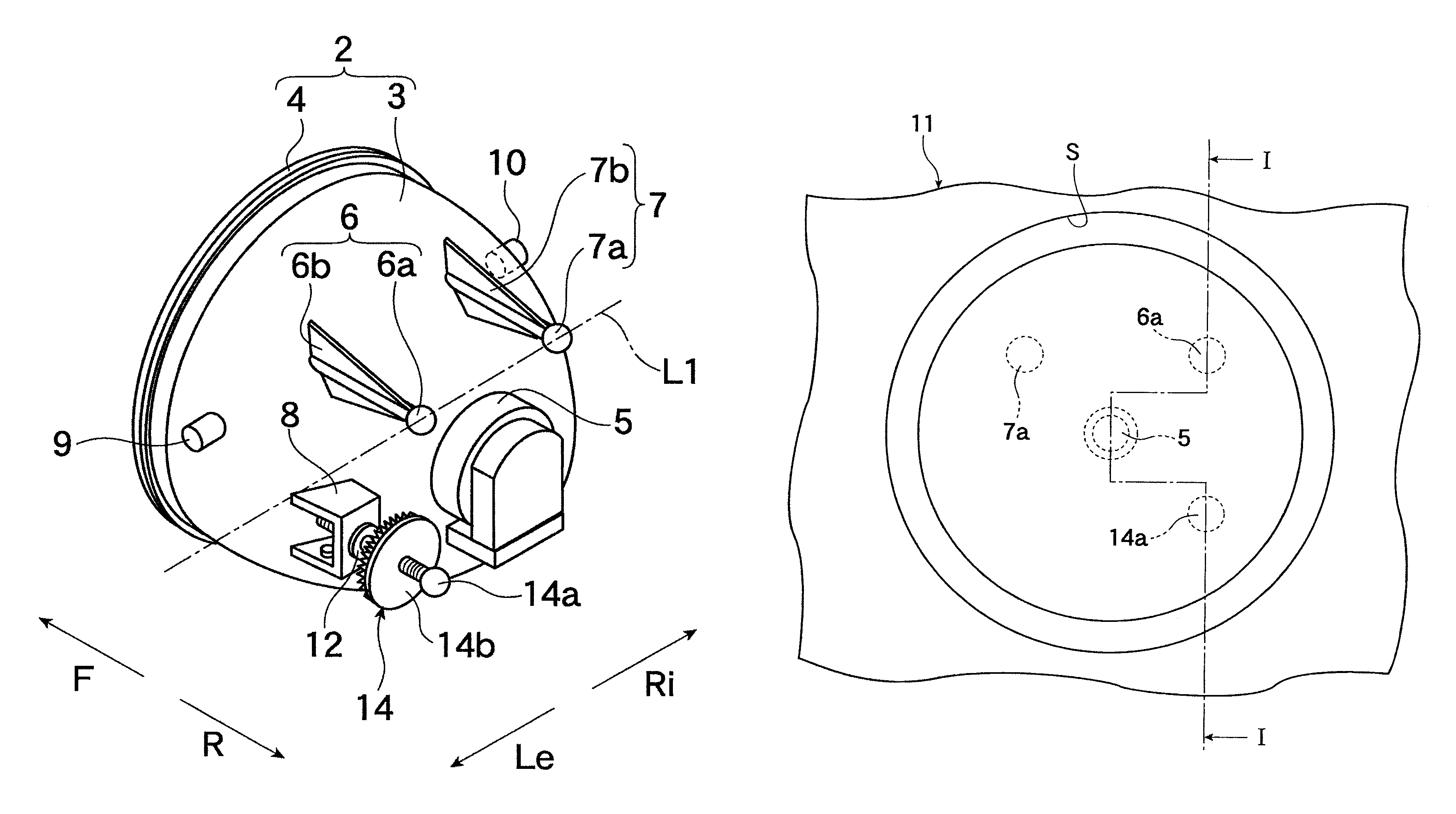
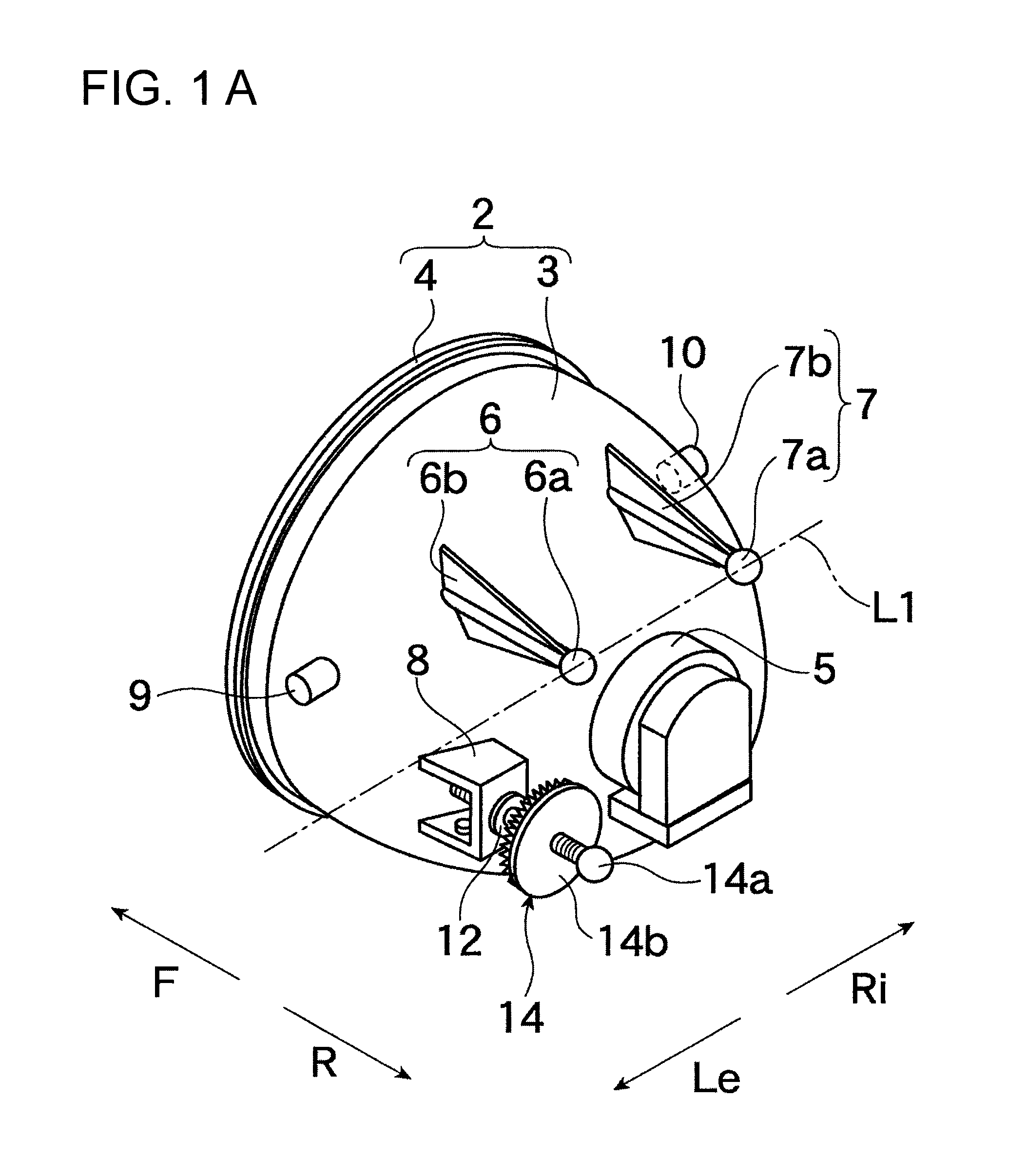
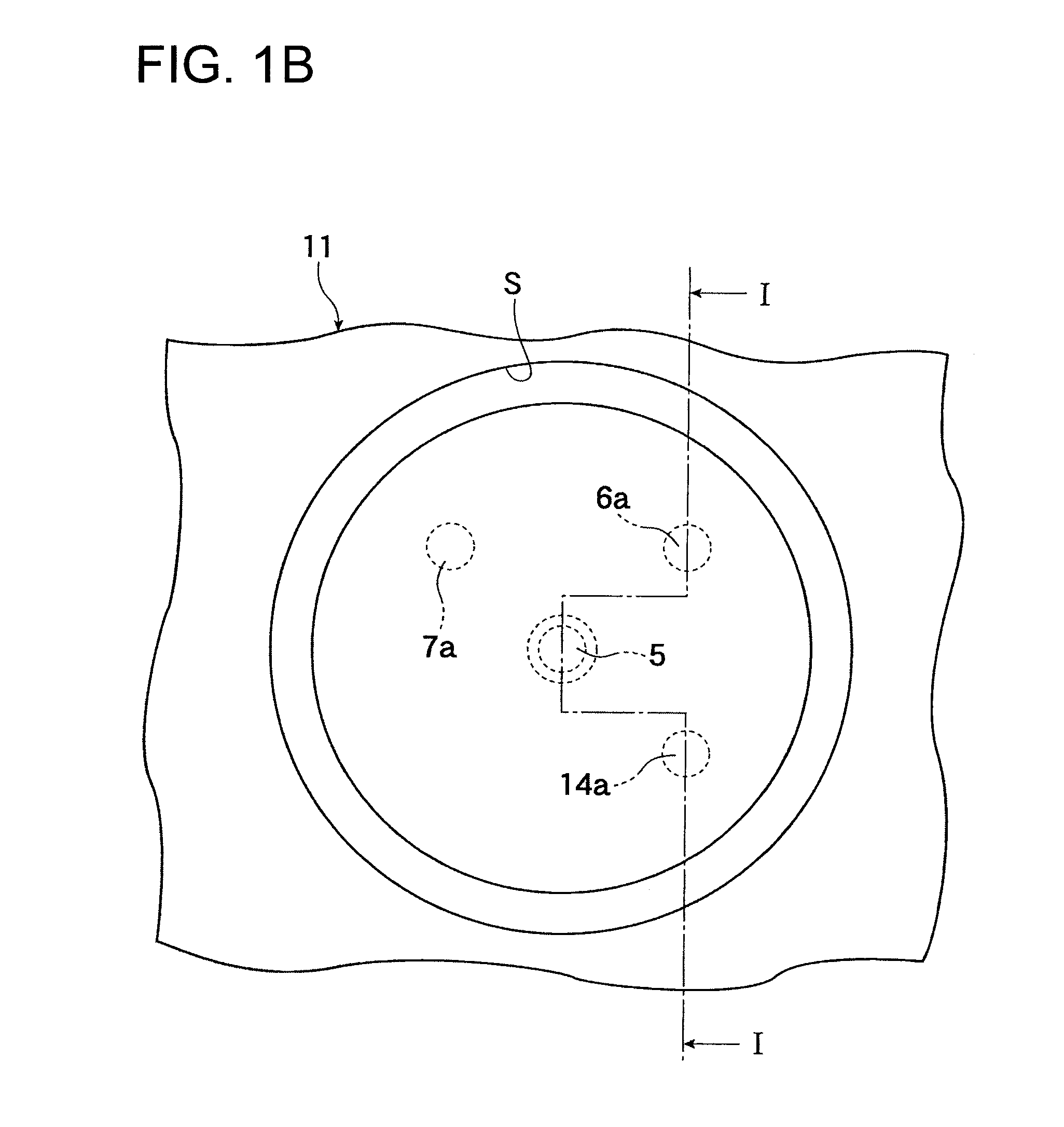
[0033]First, a first aiming mechanism 110 in which a lamp unit 2 is mounted to a vehicle body 11 from the front of the vehicle body (the outside of the vehicle body) will be described with reference to FIGS. 1A to 3. The first aiming mechanism 110 is formed by first tilt axis structural members 6, 7 provided on rear portions 3a, 3b of a lamp body 3 of the lamp unit 2, and an optical axis adjusting portion 8 in which an aiming screw 14 is rotatably attached such that a rotational axis becomes substantially parallel to the vehicle body longitudinal direction.

[0034]FIG. 1A and FIG. 2 show the lamp unit 2 of a vehicular lamp 1 of one or more embodiments of the present invention that is formed aim-adjustable. The lamp unit 2 is a fog lamp or the like, and is formed by a resin lamp body 3 with a bulb 5 that serves as a light source fitted in the center inside, and a transparent or semi-t...


PUM


Abstract

A vehicular lamp includes a first aiming mechanism and a second aiming mechanism that enable a lamp unit to be assembled to a vehicle body from the outside or the inside. The lamp body includes a pair of first vertical tilt axis structural members that are provided on a rear portion and engage with the vehicle body tiltably around a first horizontal tilt axis, and a pair of second vertical tilt axis structural members that are provided on both left and right sides and retained tiltably around a second horizontal tilt axis with respect to the vehicle body. The first aiming mechanism has a first optical axis adjusting portion that tilts the lamp unit around the first horizontal tilt axis via an aiming screw. The second aiming mechanism has a second optical axis adjusting portion that tilts the lamp unit around the second horizontal tilt axis via an aiming screw.

Description

BACKGROUND OF INVENTION[0001]1. Field of the Invention[0002]The present invention relates to a vehicular lamp in which a lamp unit pivots vertically by an aiming mechanism.[0003]2. Related Art[0004]Patent Document 1 describes a movable unit type vehicular headlamp (see FIGS. 1, 3, 5, 6 of Patent Document 1). The vehicular headlamp in Patent Document 1 is such that a lamp unit in which a front lens is mounted to a lamp body provided with a reflector and a bulb that is a light source on the inside is tiltably supported about a horizontal tilt axis by a pair of left and right axial supporting portions of a lamp housing that surrounds the unit in a U-shape. Also, the lamp unit is tilt-adjusted about the horizontal tilt axis by turning an aiming screw that is arranged between a horizontal arm that extends horizontal to a back surface side of the lamp body and a horizontal step portion of the lamp housing, such that an optical axis is tilt-adjusted in the vertical direction.[0005]Also, a ...

Claims


Application Information

Patent Timeline
Patent Type & Authority Patents(United States)
IPC IPC(8): G01B21/22F21W107/10F21Y101/00
CPCB60Q1/0683
Inventor NISHITANI, NORIHIRO
Owner KOITO MFG CO LTD
Why Eureka
Try Eureka