Lamp and lighting fixture

a technology for lighting fixtures and lamps, applied in the field of lamps, can solve the problems of reducing the efficiency of lamps, and increasing the back reflection of lamps

Active Publication Date: 2017-07-18
SIGNIFY HLDG BV
View PDF2 Cites 0 Cited by
  • Summary
  • Abstract
  • Description
  • Claims
  • Application Information

AI Technical Summary

Benefits of technology

[0007]The openings in the carrier increases the optical efficiency of the lamp, since light reflected back from the cover member otherwise may be absorbed in the carrier. Especially if the optical function of the cover member is strong (meaning strong light manipulation such as beam shaping or scattering), the associated back reflection is increased. Furthermore, since less or no light is absorbed in the carrier, the temperature of the carrier and the light sources may be lowered, which in turn may extend the life time of the lamp.
[0009]Said series of solid state light sources may be located on one side of the carrier, wherein another series of solid state light sources is mounted (and correspondingly located) on the opposite side of the carrier. In this embodiment, light generated on one side can mix with the light on the opposite side, thus improving the mixing behavior of the lamp.
[0010]The openings can facilitate color or flux mixing, reducing the requirements on the optical function of the cover member, which in turn may reduce the cost of the lamp. The lamp may further comprise another cover member covering said another series of solid state light sources, wherein the carrier is positioned between the two cover members.
[0012]The width of the openings may substantially correspond to the width of the solid state light sources. The width of the openings may for example be between 80% and 120% of the width of the solid state light sources. The length of the openings substantially may correspond to the distance between successive solid state light sources of said series of solid state light sources. The length of the openings may for example be between 80% and 100% of the distance between successive solid state light sources of said series of solid state light sources. Furthermore, the width and / or the length of the openings may be at least two times the thickness of the carrier. A purpose of the openings is to decrease the surface area of the carrier. However, the side walls of the openings increases the surface area, whereby the width and / or the length of the openings has / have to be large enough so that the overall surface area is decreased.
[0013]The carrier may be a single, separate, and self-supported carrier. In this way, the solid state light sources may easily be mounted on the carrier, preferably using conventional techniques, like surface-mount technology (SMT). The carrier may comprise electrical connections for the solid state light sources. The carrier may for example be a printed circuit board (PCB).

Problems solved by technology

However, the light guide sheet in CN202546362 may reflect part the light emitted by the LED lamp panel back to the LED lamp panel, thus reducing the efficiency of the lamp Especially if the optical function of the light guide sheet is strong, the associated back reflection is increased.
This lowers the efficiency of the lamp, which increases the cost of the lamp.
Also, the light absorbed by the LED lamp panel increases the temperature of the LED lamp panel, which may reduce the life time of the lamp.

Method used


Image

  • Lamp and lighting fixture
  • Lamp and lighting fixture
  • Lamp and lighting fixture

Examples


Embodiment Construction

[0021]The present invention will now be described more fully hereinafter with reference to the accompanying drawings, in which currently preferred embodiments of the invention are shown. This invention may, however, be embodied in many different forms and should not be construed as limited to the embodiments set forth herein; rather, these embodiments are provided for thoroughness and completeness, and fully convey the scope of the invention to the skilled person. Like reference numerals refer to like elements throughout.

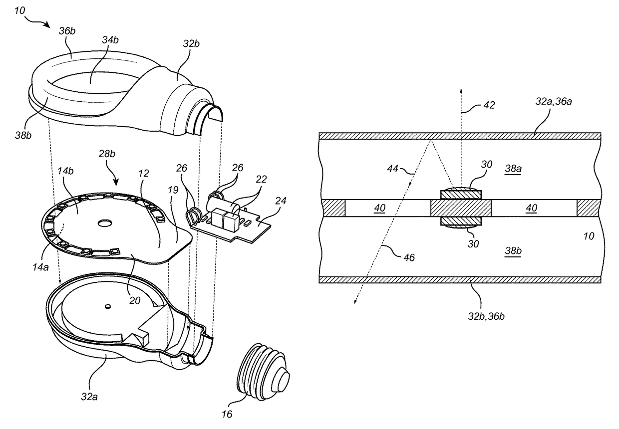
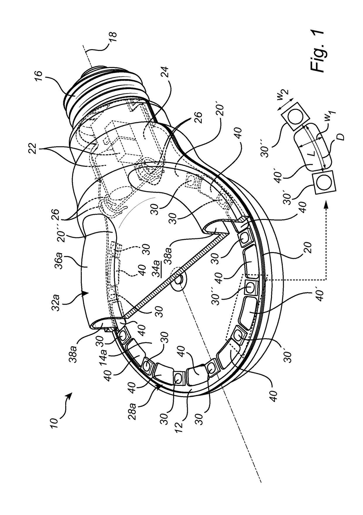
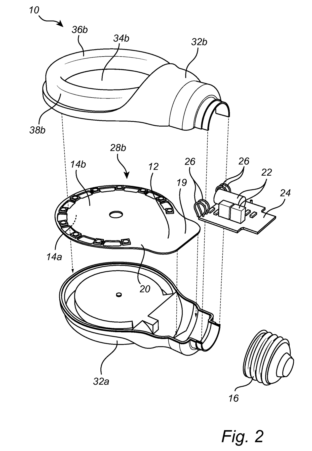
[0022]FIGS. 1-2 show a lamp 10 according to an embodiment of the present invention. The lamp 10 comprises a carrier 12. The carrier 12 is preferably a single, separate, and self-supported carrier, though other configurations are possible as well. The carrier 12 is preferably flat, with a first side 14a and a second, opposite side 14b, as well as a thickness between the first side 14a and the second side 14b. The carrier 12 may be a printed circuit board (PCB), with ...


PUM


Abstract

The present invention relates lamp (10), comprising: a carrier (12); a series (28a) of solid state light sources (30) mounted on the carrier; and a cover member (32a) covering the series of solid state light sources, wherein openings (40) are provided in the carrier between the solid state light sources of said series of solid state light sources, such that light emitted from the series of solid state light sources and reflected back towards the carrier by the cover member is allowed to pass the carrier through the openings. The present invention also relates to a lighting fixture comprising at least one such lamp.

Description

CROSS REFERENCE TO PRIOR APPLICATIONS[0001]This application is the Continuation Application under 35 USC 120 of International Application No. PCT / EP2015 / 066062, filed on Jul. 14, 2015, which claims the benefit of European Patent Application No. 14178249.0, filed on Jul. 24, 2014. These applications are hereby incorporated by reference herein.FIELD OF THE INVENTION[0002]The present invention relates to a lamp, for example a flat replacement bulb comprising light emitting diodes. The present invention also relates to a lighting fixture comprising at least one such lamp.BACKGROUND OF THE INVENTION[0003]CN202546362 discloses an LED (light emitting diode) lamp which i.a. comprises a lamp holder which is arranged at the bottom of a bulb; an LED circuit board arranged in the lamp holder; a vertically fixed LED lamp panel, wherein the LED lamp panel is electrically connected with the LED circuit board in the lamp holder through a rotating member; and a light guide sheet which is overlapped ...

Claims


Application Information

Patent Timeline
Patent Type & Authority Patents(United States)
IPC IPC(8): F21V29/00F21K9/232F21K9/23F21V23/06F21V3/04F21V19/00F21V7/00F21K99/00F21V3/02F21V23/00F21Y101/00F21Y105/10F21Y105/12F21Y107/20F21Y107/90F21Y115/10
CPCF21K9/232F21K9/23F21V3/02F21V3/04F21V7/0016F21V19/003F21V23/06F21V23/006F21Y2101/00F21Y2105/10F21Y2105/12F21Y2107/20F21Y2107/90F21Y2115/10F21K9/238F21K99/00
Inventor BUKKEMS, PETER JOHANNES MARTINUSWEIJERS, ALDEGONDA LUCIA
Owner SIGNIFY HLDG BV
Why Eureka
Try Eureka