Variable focal length lens and lens array comprising discretely controlled micromirrors

Active Publication Date: 2006-01-19
STEREO DISPLAY
View PDF12 Cites 62 Cited by
  • Summary
  • Abstract
  • Description
  • Claims
  • Application Information

AI Technical Summary

Benefits of technology

[0018] The advantages of the present invention are: (1) the DCMAL has a large focal length variation because a large numerical aperture variation can be achieved by increasing the maximum rotational angle of the DCM; (2) The driving voltage is low. Therefore, the DCMAL is fully compatible with known IC circuit operation and semiconductor microelectronics technologies; (3) the DCMAL has very fast response time because each DCM has a tiny mass; (4) the DCMAL has a high optica

Problems solved by technology

The snap-down phenomenon reduces the useful ranges of translation and rotation.
The high driving voltage is also a disadvantage of the conventional electrostatic micromirrors in practical use.
The inaccuracy of the mirror displacement is another important disadvantage of the conventional electrostatic micromirrors.
Therefore, the conventional micromirror array lens, which is described in “Fast-respon

Method used


Image

  • Variable focal length lens and lens array comprising discretely controlled micromirrors
  • Variable focal length lens and lens array comprising discretely controlled micromirrors
  • Variable focal length lens and lens array comprising discretely controlled micromirrors

Examples


Embodiment Construction

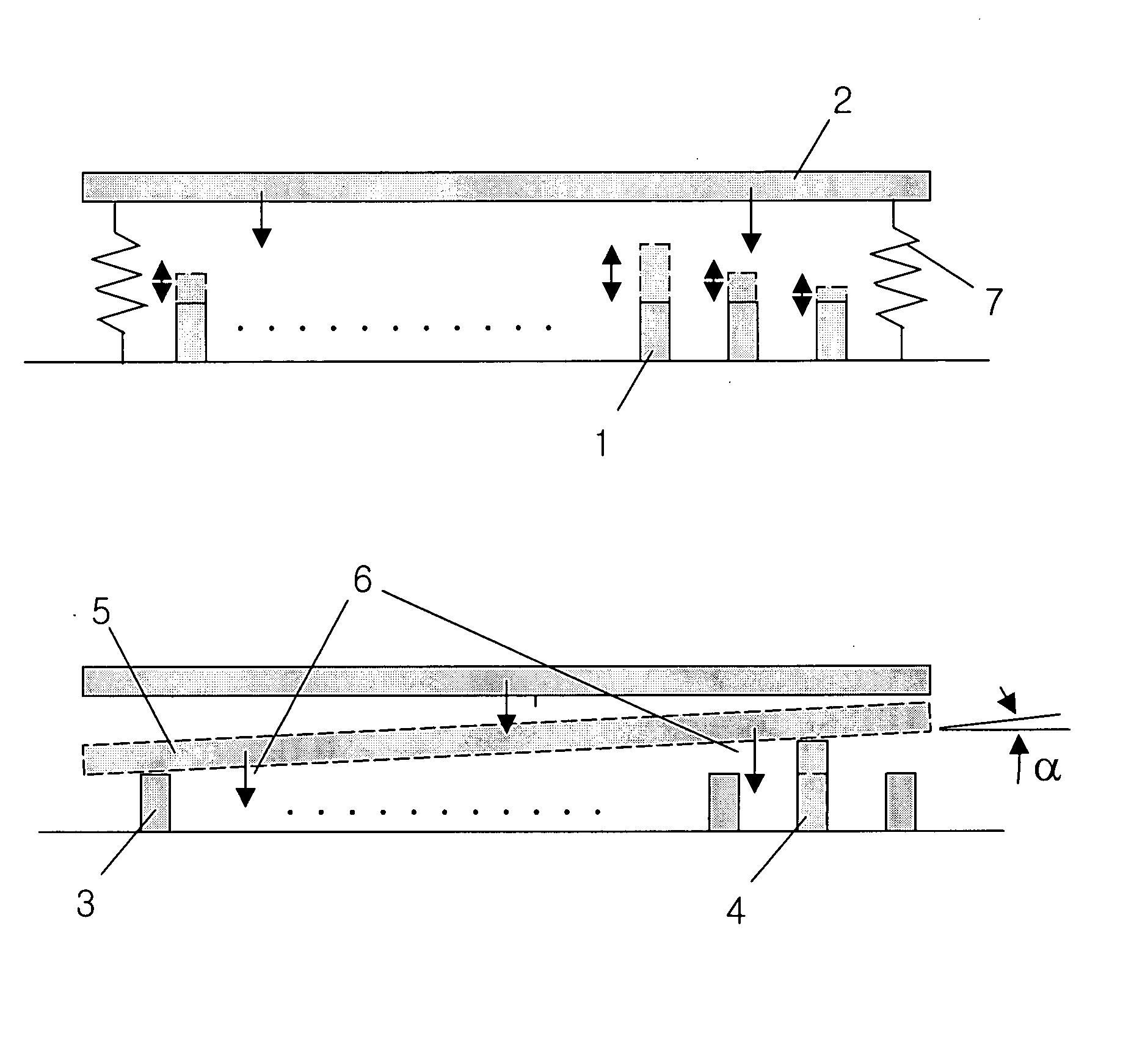
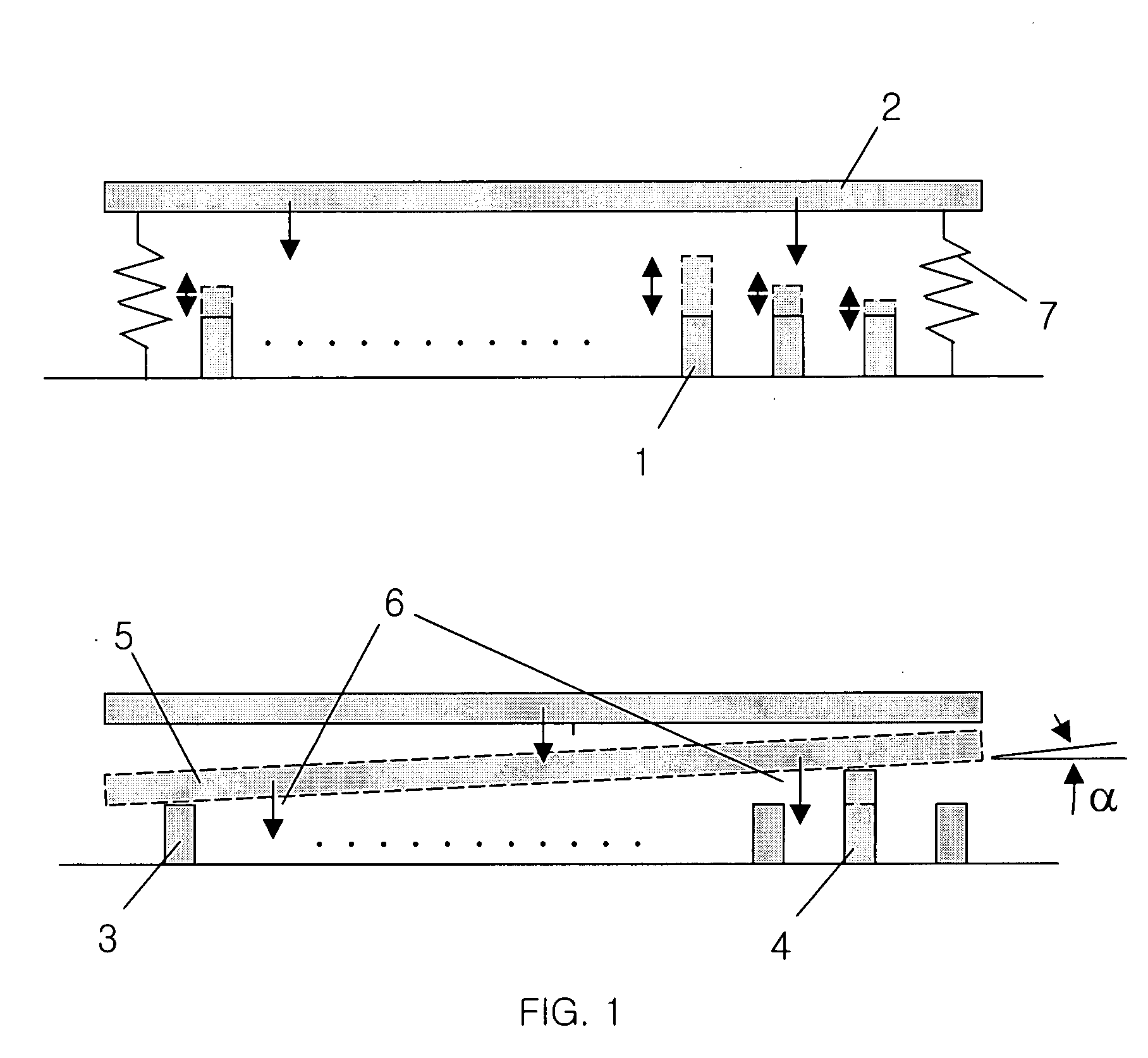
[0034]FIG. 1 shows the concept of the DCM with the variable supports 1. The variably supported discretely controlled micromirror (VSDCM) uses supports 1 providing gaps of various width through which the micromirror can move. The supports 1 are located under the micromirror 2. Translation and rotation of the VSDCM are determined by combinations of gaps, which are determined by variable supports 3, 4 on which the micromirror 5 rests. Gaps determined by the variable supports are controlled and the micromirror rests on the controlled supports 3, 4 by attractive force 6. Therefore, the combination of gaps which the supports 3, 4 provide determines translation and rotation of the micromirror 2. Gap variation by the supports 3, 4 is determined by bistable motions of the supports 3, 4 and the motions are controlled by digital voltage. The position of micromirror 5 is restored to its initial position by the force of flexible spring 7 when the attractive force is off.

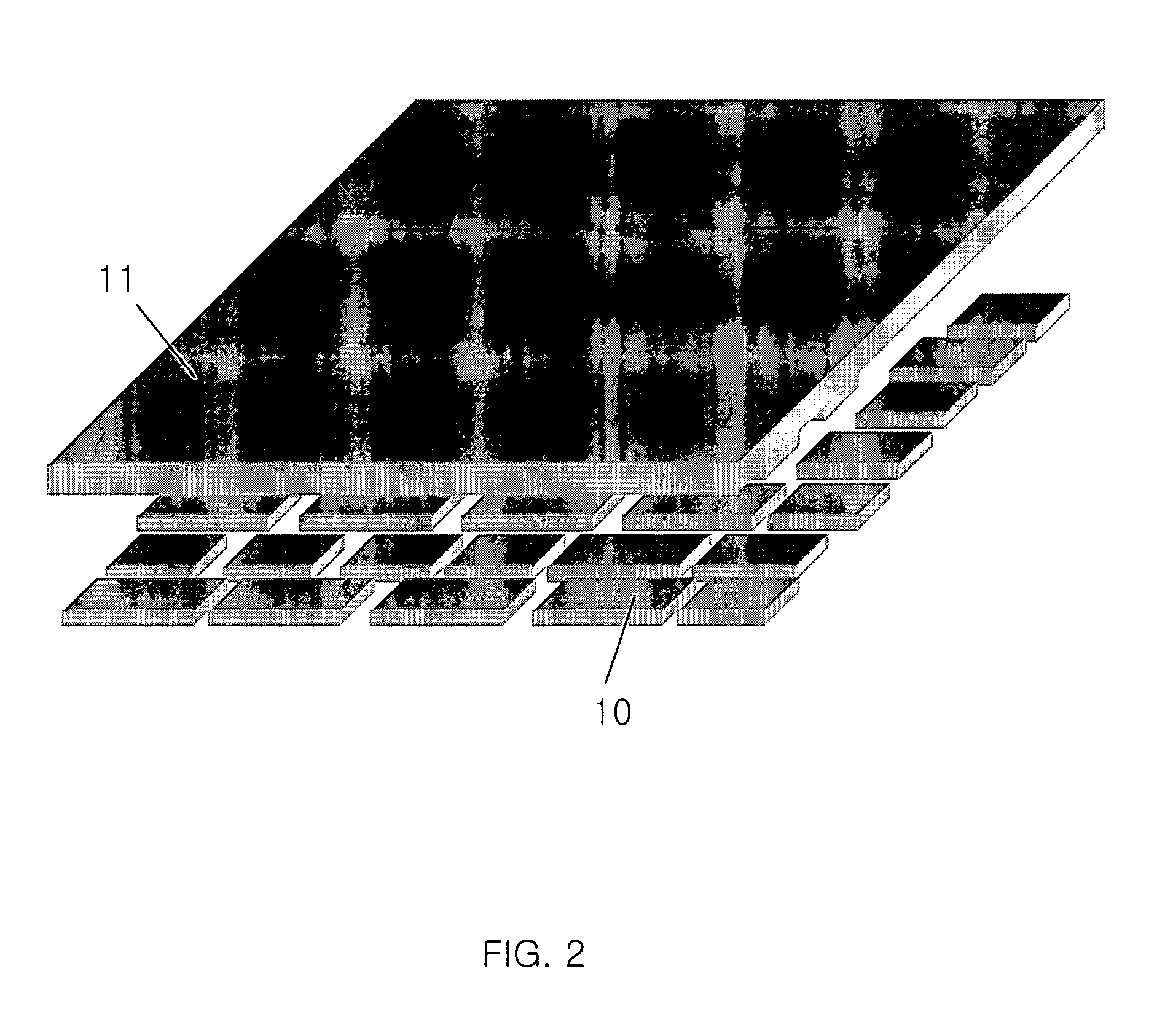
[0035]FIG. 2 shows anoth...


PUM


Abstract

A discretely controlled micromirror array lens (DCMAL) consists of many discretely controlled micromirrors (DCMs) and actuating components. The actuating components control the positions of DCMs electrostatically. The optical efficiency of the DCMAL is increased by locating a mechanical structure upholding DCMs and the actuating components under DCMs to increase an effective reflective area. The known microelectronics technologies can remove the loss in effective reflective area due to electrode pads and wires. The lens can correct aberrations by controlling DCMs independently. Independent control of each DCM is possible by known microelectronics technologies. The DCM array can also form a lens with arbitrary shape and/or size, or a lens array comprising the lenses with arbitrary shape and/or size.

Description

BACKGROUND OF THE INVENTION [0001] The present invention relates to a variable focal length lens consisting of a discretely controlled micromirror (DCM) array and operational methods for controlling the DCM array. [0002] A widely used conventional variable focal length system makes use of two refractive lenses. It has complex driving mechanisms to control the relative positions of the refractive lenses. This conventional system also has a slow response time. Alternatively, variable focal length lenses can be made by changing the shape of the lens, as is done in the human eye. This method has been used in lenses made with isotropic liquids. Other lenses have been made of media with an electrically variable refractive index to create either a conventional lens or a gradient index lens by means of a voltage gradient. The electrically variable refractive index allows the focal length of the lenses to be voltage controlled. Among them, the most advanced variable focal length lens is a li...

Claims


Application Information

Patent Timeline
IPC IPC(8): G02B26/00
CPCG02B3/14G02B5/09G02B26/0866G02B26/0841G02B26/0825G02B26/08G02B26/00
Inventor CHO, GYOUNG ILSEO, CHEONG SOOKIM, TAE HYEONGIM, DONG WOO
Owner STEREO DISPLAY
Why Eureka
Try Eureka