
Small and fast zoom system using micromirror array lens

a micromirror array and zoom system technology, applied in the field of optical zoom devices, can solve the problems of reducing the speed of zooming, increasing space and weight, power consumption, and possibly inducing unwanted jitter, and achieves compact zoom systems, high zooming speed, and large variation of magnification.

Active Publication Date: 2006-09-21
STEREO DISPLAY
View PDF82 Cites 8 Cited by
  • Summary
  • Abstract
  • Description
  • Claims
  • Application Information

AI Technical Summary

Benefits of technology

[0010] An objective of the invention is to provide a small and fast zoom system without macroscopic mechanical movements of lens or lenses.
[0012] Still another object of the invention is to provide a zoom system that can compensate for the aberration of the system.
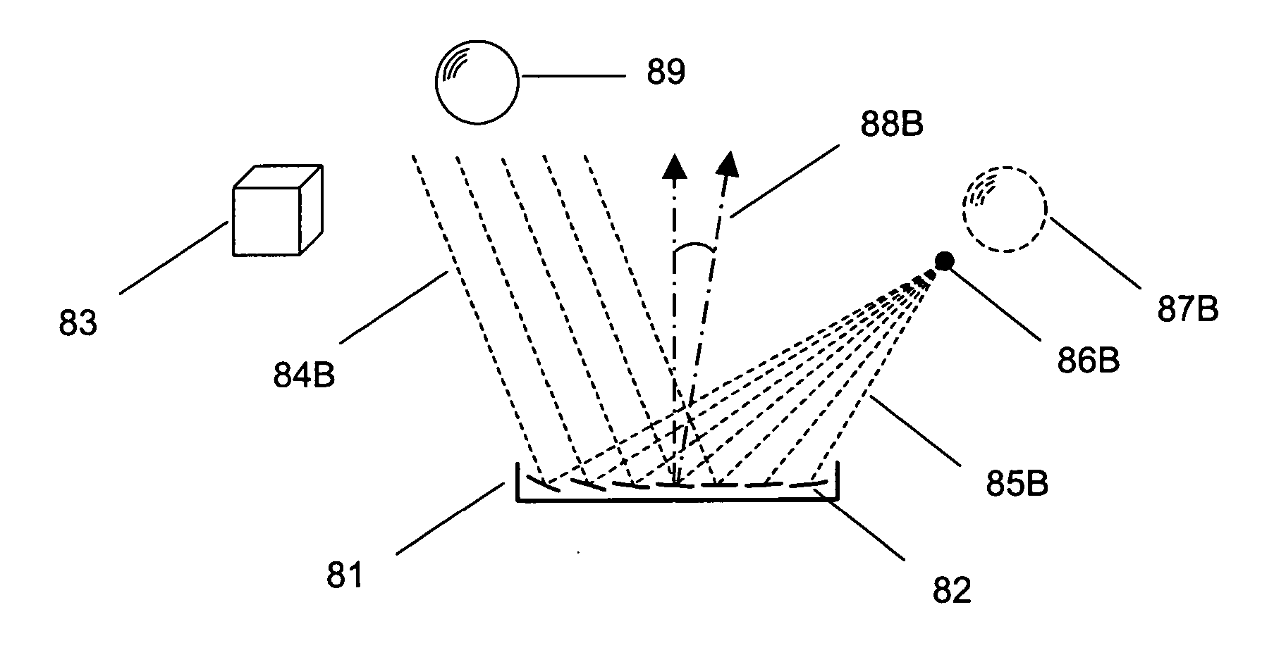
[0016] The MMAL comprising micromirrors provides a very fast response time, a large focal length variation, a high optical focusing efficiency, a simple focusing structure, low power consumption, and a low production cost thanks to the mass production advantage. Also, the MMAL is an adaptive optical component which compensates aberration of the system and changes the optical axis without macroscopic mechanical movements of lenses.
[0021] Since the MMAL is an adaptive optical element, the zoom system can compensate for the aberration of the system by controlling each micromirror of the MMAL. The aberration of the system include, but not limited to, phase errors of light introduced by the medium between an object and its image and the defects of the zoom system that may cause the image to deviate from the rules of paraxial imagery. Further, an object which does not lie on the optical axis can be imaged by the MMAL without macroscopic mechanical movements of the zoom system.
[0055] The zoom system of the present invention has advantages: (1) a compact zoom system is provided; (2) the system has a very high zooming speed; (3) the system has a large variation of magnification; (4) the system has a variable optical axis; (5) the system has a high optical efficiency; (6) the cost is inexpensive because the MMAL is inexpensive and the macroscopic mechanical movements of lenses are not necessary; (7) the system compensates for the aberration of the system; (8) the system has a very simple structure because there is no macroscopic mechanical movements of lenses; (9) the system requires small power consumption when the MMAL is actuated by electrostatic force.

Problems solved by technology

The mechanical motions decrease the speed of zooming, increase space and weight as well as the power consumption and possibly induce of unwanted jitter.
In addition, the mechanical zoom system is restricted to magnifying the area on-axis.
This system requires a high voltage, a large structure, a high manufacturing and maintenance cost, which make it difficult to implement in the small portable devices such as camera phone, PDA, portable computer, etc.
Even though the fastest response liquid crystal lens has the response time of tens of milliseconds, it has small focal length variation and low focusing efficiency.

Method used


Image

  • Small and fast zoom system using micromirror array lens
  • Small and fast zoom system using micromirror array lens
  • Small and fast zoom system using micromirror array lens

Examples


Embodiment Construction

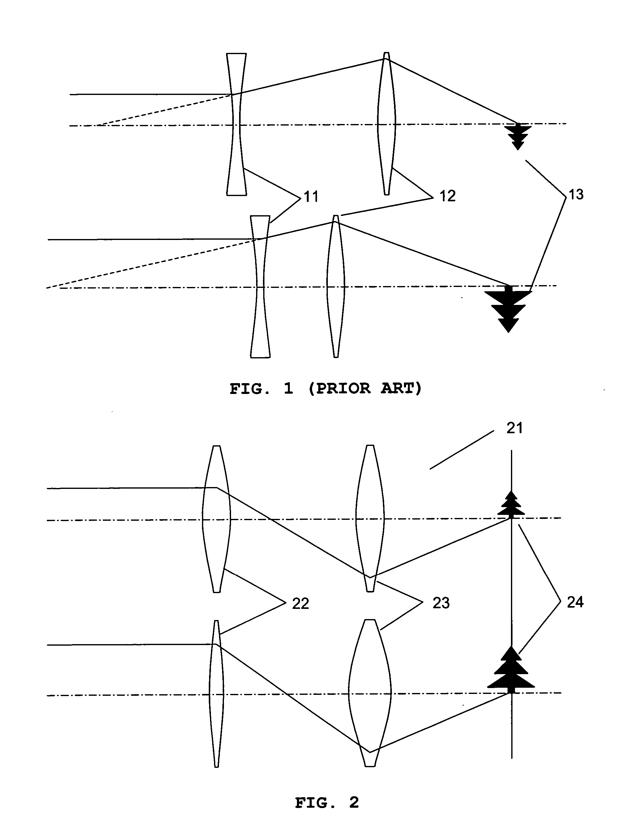
[0069]FIG. 2 shows a zoom system 21 using one or more variable focal length lenses. In the embodiment shown in FIG. 2, the zoom system includes a first variable focal length lens 22 and a second variable focal length lens 23. Changing the magnification of an imaging system is accomplished by utilizing the variable focal length lenses 22, 23. The first variable focal length lens 22 changes the image size. But, the image is defocused because the imaging position is also changed. Therefore, the focal length of the two variable focal length lenses 22, 23 must be changed in unison to magnify and keep the image 24 in-focus.

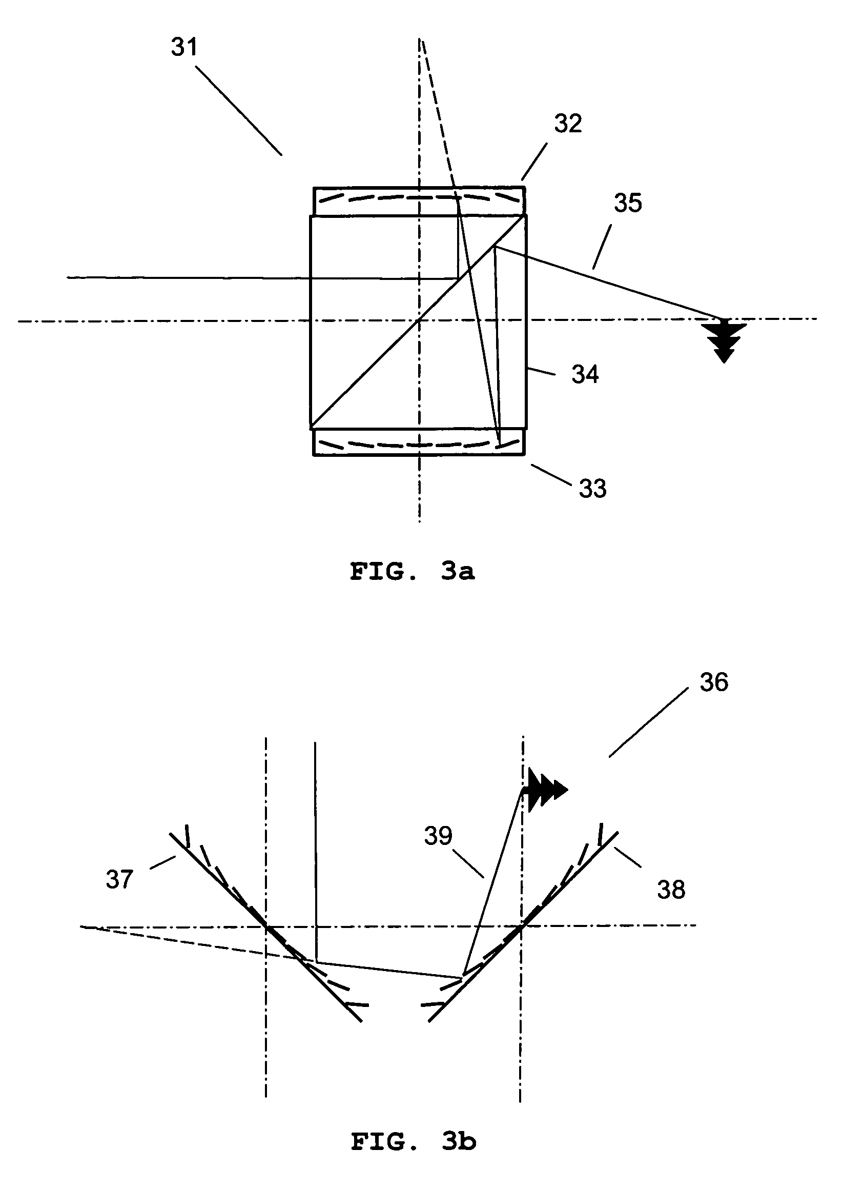
[0070]FIG. 3a shows a zoom system 31, in which MMALs 32 and 33 are used as variable focal length lenses 32 and 33. Since the MMALs 32 and 33 are reflective types, it is impossible to make an in-line optical arrangement without additional optical elements. Therefore, the zoom system 31 includes a beam splitter 34 positioned in the path of light 35 between the first MMAL...


PUM


Abstract

The present invention provides a small and fast zoom system using micromirror array lens (MMAL). Thanks to the fast response and compactness of the MMAL as well as absence of the macroscopic mechanical movements of lenses, the zoom system of the present invention fastens the speed of the zooming and reduces the space and weight for the zoom system. Also the present invention provides magnifying the area not on the optical axis and can compensate the aberration of the zoom system.

Description

REFERENCE TO RELATED APPLICATIONS [0001] This application is a continuation-in-part of, and claims priority to U.S. patent application Ser. No. 10 / 806,299 filed Mar. 22, 2004, U.S. patent application Ser. No. 10 / 855,715 filed May 27, 2004, U.S. patent application Ser. No. 10 / 872,241 filed Jun. 18, 2004, U.S. patent application Ser. No. 10 / 893,039 filed Jul. 16, 2004, U.S. patent application Ser. No. 10 / 983,353 filed Nov. 8, 2004, U.S. patent application Ser. No. 10 / 896,146 filed Jul. 21, 2004, U.S. patent application Ser. No. 11 / 072,597 filed Mar. 4, 2005, U.S. patent application Ser. No. 11 / 076,616 filed Mar. 10, 2005, U.S. patent application Ser. No. 11 / 191,886 filed Jul. 28, 2005, U.S. patent application Ser. No. 11 / 218,814 filed Sep. 2, 2005, and U.S. patent application Ser. No. 11 / 369,797 filed Mar. 6, 2006, all of which are hereby incorporated by reference.FIELD OF INVENTION [0002] The present invention relates to an optical zoom device and operational methods for the device. ...

Claims


Application Information

Patent Timeline
IPC IPC(8): G02B15/14G02B5/08
CPCG02B17/0694G02B17/0896G02B26/0833
Inventor KIM, HYE YOUNGSOHN, JIN YOUNGCHO, GYOUNG ILBAEK, SANG HYUNESEO, CHENONG SOO
Owner STEREO DISPLAY
Learn More