Pressure test device for pipe fittings

A technology for pressure testing and pipe fittings, which is applied in the direction of pipe components, measuring devices, pipes/pipe joints/pipe fittings, etc., which can solve the problems of heavy welding workload, difficulty, and many processing procedures, and achieve compactness of the whole machine, cost savings, and The effect of easy operation

Active Publication Date: 2014-04-02
TIANJIN LVQING PIPELINE TECH CO LTD
View PDF7 Cites 18 Cited by
  • Summary
  • Abstract
  • Description
  • Claims
  • Application Information

AI Technical Summary

Problems solved by technology

[0003] The existing technical solutions have the following disadvantages: 1) Non-standard heads need to be customized, and material waste is serious; 2) Welding regenerates welding stress on heat-treated elbows, which affects the quality of pipe fittings; 3) The welding workload is large and the efficiency is low; 4) There are many processing procedures and it is difficult

Method used


Image

  • Pressure test device for pipe fittings
  • Pressure test device for pipe fittings
  • Pressure test device for pipe fittings

Examples


Embodiment 1

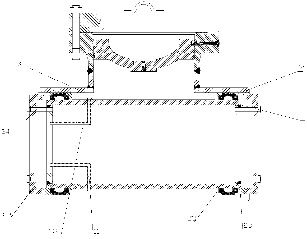
[0025] Embodiment 1 Pipe fitting pressure test device is used for tee pressure test

[0026] The pressure test steps are as follows:

[0027] a. The pressure test tube 1 with both ends open is installed in the straight pipe of the tee 3. If the tee 3 is a tee with holes, it is necessary to block the opening without the plugging head; then press the flange 23. The sealing ring 21 and the connection plate 22 are set on the outer walls of both ends of the pressure test tube 1 according to the preset method, the bolts 24 are installed, and the bolts 24 are rotated to make the flange pressure plate 23 compress the sealing ring 21, and the sealing ring 21 deforms radially. Thereby it fits tightly with the inner wall of the tee 3, so that the outer wall of the pressure test tube 1 and the inner wall of the tee 3 form a closed cavity. (like figure 1 shown) If pre-tightening is required, a pre-tightening device must be used to set the pre-tightening before rotating the bolt 24;

[0...

Embodiment 2

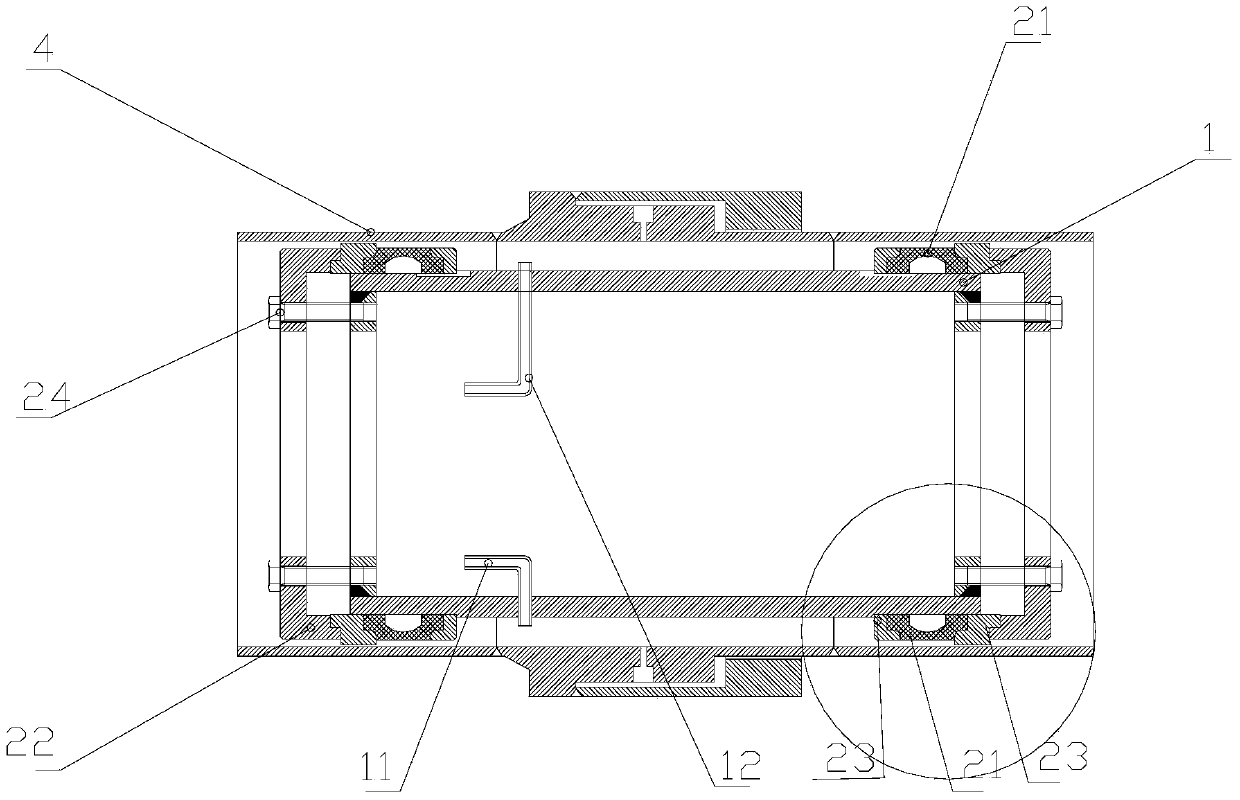
[0033] Example 2 The pipe fitting pressure test device is used for the pressure test of the insulating pup joint

[0034]The pressure test steps are as follows:

[0035] a. Install the pressure test tube 1 with both ends open in the insulating nipple 4; then put the flange pressure plate 23, sealing ring 21, and connection plate 22 on the outer walls of the two ends of the pressure test tube 1 according to the preset method, Install the bolt 24, rotate the bolt 24 to make the flange pressure plate 23 compress the sealing ring 21, and the sealing ring 21 deforms radially, so as to fit tightly with the inner wall of the insulating nipple 4, so that the outer wall of the pressure test tube 1 and the inner wall of the insulating nipple 4 form a A closed cavity. (like figure 2 and Figure 4 shown) If pre-tightening is required, a pre-tightening device must be used to set the pre-tightening before rotating the bolt 24;

[0036] b. Connect the water injection pipe joint leading ...

Embodiment 3

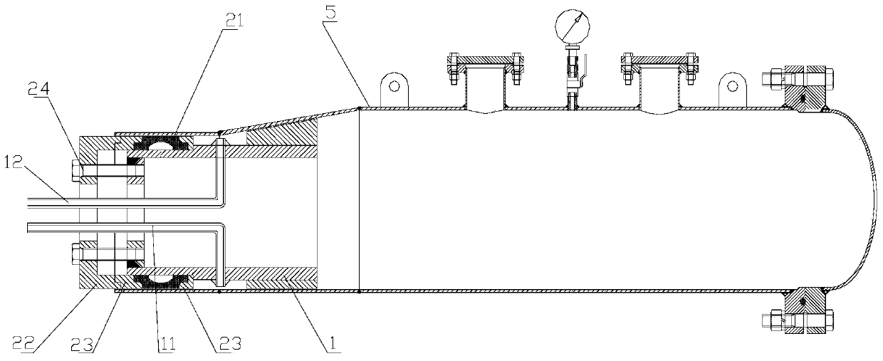
[0041] Embodiment 3 The pipe fitting pressure test device is used for the pressure test of the receiving and receiving spherical cylinder

[0042] The pressure test steps are as follows:

[0043] a. The pressure test tube 1 with one end open is installed in the receiving and receiving spherical cylinder 5, and the open end is close to the opening of the receiving and receiving spherical cylinder 5; Go out of the outlet of the receiving and receiving ball barrel 5; then put the flange pressure plate 23, the sealing ring 21, and the connection plate 22 on the outer walls of the two ends of the pressure test tube 1 according to the preset method, install the bolt 24, and rotate the bolt 24 to make the flange The pressure plate 23 compresses the sealing ring 21, and the sealing ring 21 radially deforms, thereby closely fitting with the inner wall of the receiving and receiving ball barrel 5, so that the outer wall of the pressure test tube 1 and the inner wall of the receiving and...


PUM


Abstract

The invention discloses a pressure test device for pipe fittings. The device comprises a pressure test cylinder and sealing plugs fitting the pressure test cylinder. One end or both ends of the pressure test cylinder are open. An inflow pipe and an overflow pipe whereby the inside and outside of the pressure test cylinder are communicated are arranged on the inner wall of the pressure test cylinder. The plug comprises sealing structures with a seal ring, and a connecting disc. The sealing structures enclose the pressure test cylinder. The outer wall of the pressure test cylinder is provided with clamping projections or steps fitting the sealing structures. The connecting disc is connected with the sealing structures. The pressure test device for pipe fittings has the advantages that materials are saved, pressure test is efficient, welding the plugs at two ends of a pipe fitting is not required, the two sealing plugs are connected through a middle connecting pipe, and the pressure test device for pipe fittings is structurally ingenious, simple and handy.

Description

technical field [0001] The invention relates to a pipe fitting pressure testing device. Background technique [0002] In the existing technology, the pressure test of pipe fittings such as openings, plugging tees, insulating pup joints, and receiving and receiving balls is generally welded to both ends of the head, and a water inlet pipe and a pressure gauge are installed on one end of the head. After the pressure test is over, cut off the heads welded at both ends. There is also a pressure test plan to process the sealed end faces (about 100mm) at both ends of the tee through a lathe, which requires roundness and smoothness. delivery requirements. [0003] The existing technical solutions have the following disadvantages: 1) Non-standard heads need to be customized, and material waste is serious; 2) Welding regenerates welding stress on heat-treated elbows, which affects the quality of pipe fittings; 3) The welding workload is large and the efficiency is low; 4) There ar...

Claims


Application Information

Patent Timeline
Patent Type & Authority Applications(China)
IPC IPC(8): F16L55/11G01M3/28
CPCG01M3/2807G01M3/2853G01M3/2884
Inventor 石建忠
Owner TIANJIN LVQING PIPELINE TECH CO LTD
Why Eureka
Try Eureka