Air supply device and air conditioner using same

A technology of air supply device and blower, which is applied in the direction of pump device, air conditioning system, application, etc. It can solve the problems of labor-intensive assembly and adjustment, unpleasantness, and high cost, so as to improve maintenance performance, reduce ventilation resistance, and small air duct resistance Effect

Inactive Publication Date: 2006-03-29
HITACHI APPLIANCES INC
View PDF4 Cites 18 Cited by
  • Summary
  • Abstract
  • Description
  • Claims
  • Application Information

AI Technical Summary

Problems solved by technology

Like this, just can't be in the lower part or the upper part of ventilation blower, be provided with the space required for necessary parts such as the control part of the electric component that accommodates indoor unit, and indoor unit also has to increase.
[0026] In the air conditioner of Patent Document 4, although an air duct switching mechanism with supply and exhaust components is disclosed, it is installed in an outdoor unit whose size is much smaller than that of an indoor unit. In other words, its setting position, size, etc. do not have those problems that are set in the indoor unit
[0027] In addition, in the air conditioner of Patent Document 4, although the switching of the air passage during air supply and exhaust is disclosed, the filter for removing various pollutants in the air sucked from outside the house during air supply , without mentioning at all, of course, the problem that the supplied air would be unpleasant to those who live indoors
In addition, in the description of Patent Document 4, although a "filter" is also mentioned, this "filter" is only a filter for reducing noise, not a filter for purifying the supplied air.
[0028] In addition, in the air conditioner disclosed in Patent Document 4, the air duct switching mechanism uses many gears, and the number of parts is large, so assembling and adjusting must be labor-intensive, which is a very expensive structure.
In addition, in the air conditioner of patent document 4, there is only one air duct, which is a structure that can only simply switch the direction of supply and exhaust, and it is not mentioned that it can develop in the direction of multi-functional ventilation

Method used


Image

  • Air supply device and air conditioner using same
  • Air supply device and air conditioner using same
  • Air supply device and air conditioner using same

Examples


Embodiment Construction

[0082] Next, various embodiments of the blower device of the present invention and an air conditioner using the blower device will be described with reference to the drawings.

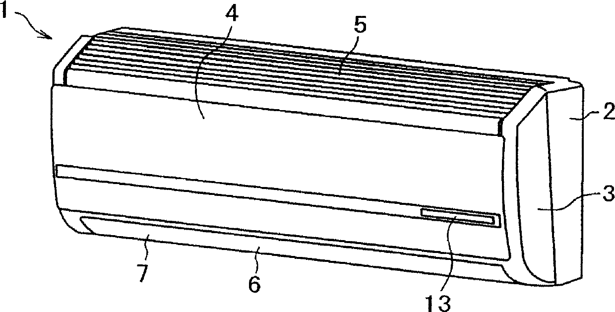
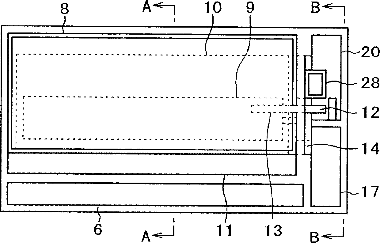
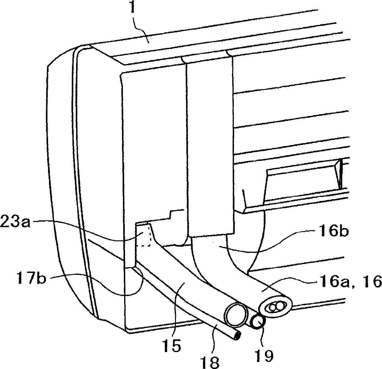
[0083] The overall structure of the air conditioner will be described with reference to FIGS. 1 to 5 . Fig. 1 is an external view of an indoor unit of an air conditioner according to an embodiment of the present invention; Fig. 2 is a front view showing the internal arrangement of main parts of the indoor unit of Fig. 1; Fig. 3 is a view of the indoor unit of Fig. 1 viewed from behind Figure 4 is a cross-sectional view along the A-A line of Figure 1; Figure 5 is a cross-sectional view along the B-B line of Figure 1.

[0084] As shown in FIG. 1 , the structure of the indoor unit 1 includes: a frame body 2 , a decorative cover 3 and a front cover 4 . In order to adjust the temperature and humidity of the indoor air, above and below the indoor unit 1, there are main suction inlets 5 for sucking in indoor...


PUM


Abstract

To provide a small blowing device of high reliability, simple in constitution and capable of switching to air supply and exhaust. The blowing device 20 is provided with a blower section 50 and an air course switching device 40 for switching to an air course for supplying outdoor air into a room, and to an air course for exhausting indoor air to the outdoors. The blower section 50 is provided with a centrifugal blower 33 for sucking air from an axial direction and blowing off air in a circumferential direction, a suction chamber 31 formed larger than a suction port of the blower 33, and a blowoff chamber 32 formed on the blowoff side of the blower 33. The air course switching device 40 is provided with an outer shell 46 having a plurality of openings, an air course switching body 41 turnably arranged in the outer shell 46 and having a partition wall for dividing the inside into a plurality of air courses, and a driving device 47 for turning the air course switching body 41 to switch communication between the plurality of air courses of the air course switching body 41 and the plurality of openings of the outer shell 46. The air course switching device 47 is juxtaposed to overlap the suction chamber 31 of the blower section 50.

Description

technical field [0001] The invention relates to an air supply device and an air conditioner using the air supply device, in particular to an air supply device for ventilation used in an indoor unit assembled in a split type air conditioner, and an air supply device using the air supply device Split type air conditioner with indoor unit. Background technique [0002] In recent years, there has been criticism of the impact of harmful substances contained in building materials on human health due to the increased airtightness of housing living spaces. In addition, there is a problem that the concentration of carbon dioxide in the living space increases due to the high airtightness. These problems have become problems to be solved by air conditioners that condition indoor air. Various proposals have been made for air conditioners with a ventilating function to solve these problems. [0003] This air conditioner is described in the following patent documents: Patent Document 1...

Claims


Application Information

Patent Timeline
Patent Type & Authority Applications(China)
IPC IPC(8): F24F7/00F04D25/08F24F1/00F24F13/20F24F13/28
CPCF24F1/0022F24F13/10F24F13/28F24F1/0073
Inventor 松原荣介寺内正高矢萩健一
Owner HITACHI APPLIANCES INC
Why Eureka
Try Eureka