Variable focal length lens and lens array comprising discretely controlled micromirrors

a discrete control, variable-length technology, applied in the direction of mirrors, mountings, instruments, etc., can solve the problems of reducing the useful range of translation and rotation, high driving voltage is also a disadvantage of the conventional electrostatic micromirror in practical use, and inaccuracy of mirror displacement is another important disadvantage of the conventional electrostatic micromirror, etc., to achieve large numerical aperture variation, large focal length variation, and low driving voltage

Active Publication Date: 2007-07-03
STEREO DISPLAY
View PDF12 Cites 21 Cited by
  • Summary
  • Abstract
  • Description
  • Claims
  • Application Information

AI Technical Summary

Benefits of technology

[0013]The DCMAL can be formed by a polar array of the DCMs. For the polar array, each DCM has a fan shape to increase its effective reflective area so that the optical efficiency increases. The optical efficiency of the DCMAL can be improved by locating a mechanical structure supporting a micromirror and the actuating components under the micromirror to increase its effective reflective area. Electric circuits to operate the DCM can be made with known MOS and CMOS technologies, which are widely used in microelectronics. By applying the microelectronics circuits under the micromirror array, the effective reflective area can be increased by removing the area that is required for electrode pads and wires. The aberration of the DCMAL can also be reduced by using DCMs with curved surfaces.
[0016]By controlling each DCM independently, the lens can correct aberration, which is caused by optical effects due to the medium between the object and its image or is caused by defects of a lens system that cause its image to deviate from the rules of paraxial imagery. Independent control of each DCM is made possible by making electric circuits required for control with known microelectronics technologies and fabricating the circuits underneath the micromirrors using known microfabrication methods.
[0018]The advantages of the present invention are: (1) the DCMAL has a large focal length variation because a large numerical aperture variation can be achieved by increasing the maximum rotational angle of the DCM; (2) The driving voltage is low. Therefore, the DCMAL is fully compatible with known IC circuit operation and semiconductor microelectronics technologies; (3) the DCMAL has very fast response time because each DCM has a tiny mass; (4) the DCMAL has a high optical focusing efficiency; (5) the DCMAL can have a large size aperture without losing optical performance. Because the DCMAL consists of discrete micromirrors, increasing the DCMAL size does not cause the an increase of aberration caused by lens shape error; (5) the DCMAL has a low cost because of the advantages of its mass productivity; (6) the DCMAL can correct aberration; (7) the DCMAL makes the focusing system very simple; (8) the DCMAL can have arbitrary shape and / or size.

Problems solved by technology

The snap-down phenomenon reduces the useful ranges of translation and rotation.
The high driving voltage is also a disadvantage of the conventional electrostatic micromirrors in practical use.
The inaccuracy of the mirror displacement is another important disadvantage of the conventional electrostatic micromirrors.
Therefore, the conventional micromirror array lens, which is described in “Fast-response Variable Focusing Micromirror Array Lens,”Proceeding of SPIE Vol. 5055: 278-286”, J. Boyd and G. Cho, 2003, has several limitations which are a small focal length change, a high driving voltage and an incompatibility with microelectronics circuits.
These limitations are caused by using equilibrium between the electrostatic force and the elastic force to control the displacements of a micromirror.

Method used


Image

  • Variable focal length lens and lens array comprising discretely controlled micromirrors
  • Variable focal length lens and lens array comprising discretely controlled micromirrors
  • Variable focal length lens and lens array comprising discretely controlled micromirrors

Examples


Embodiment Construction

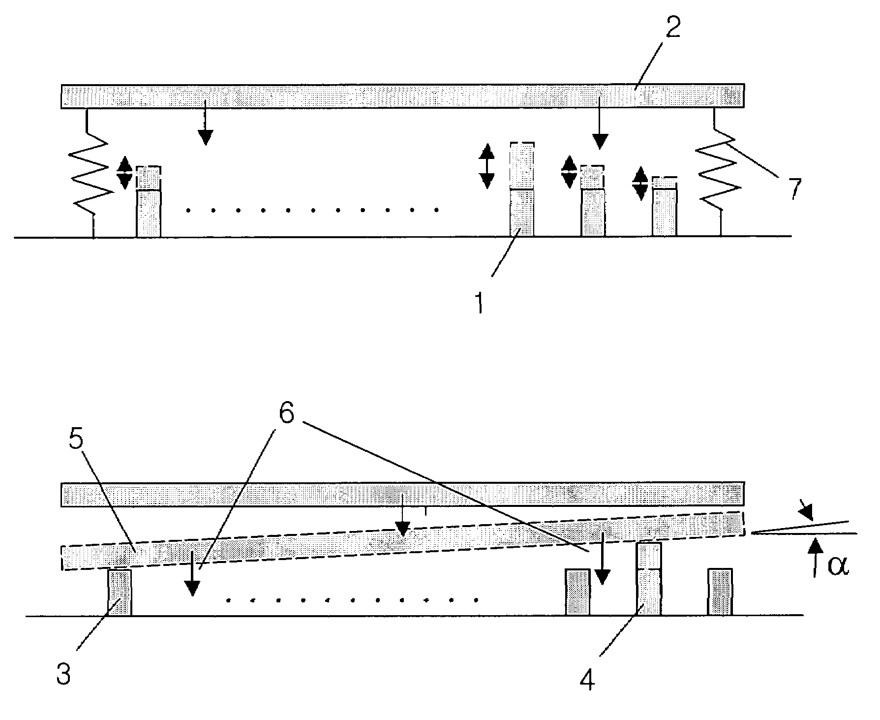
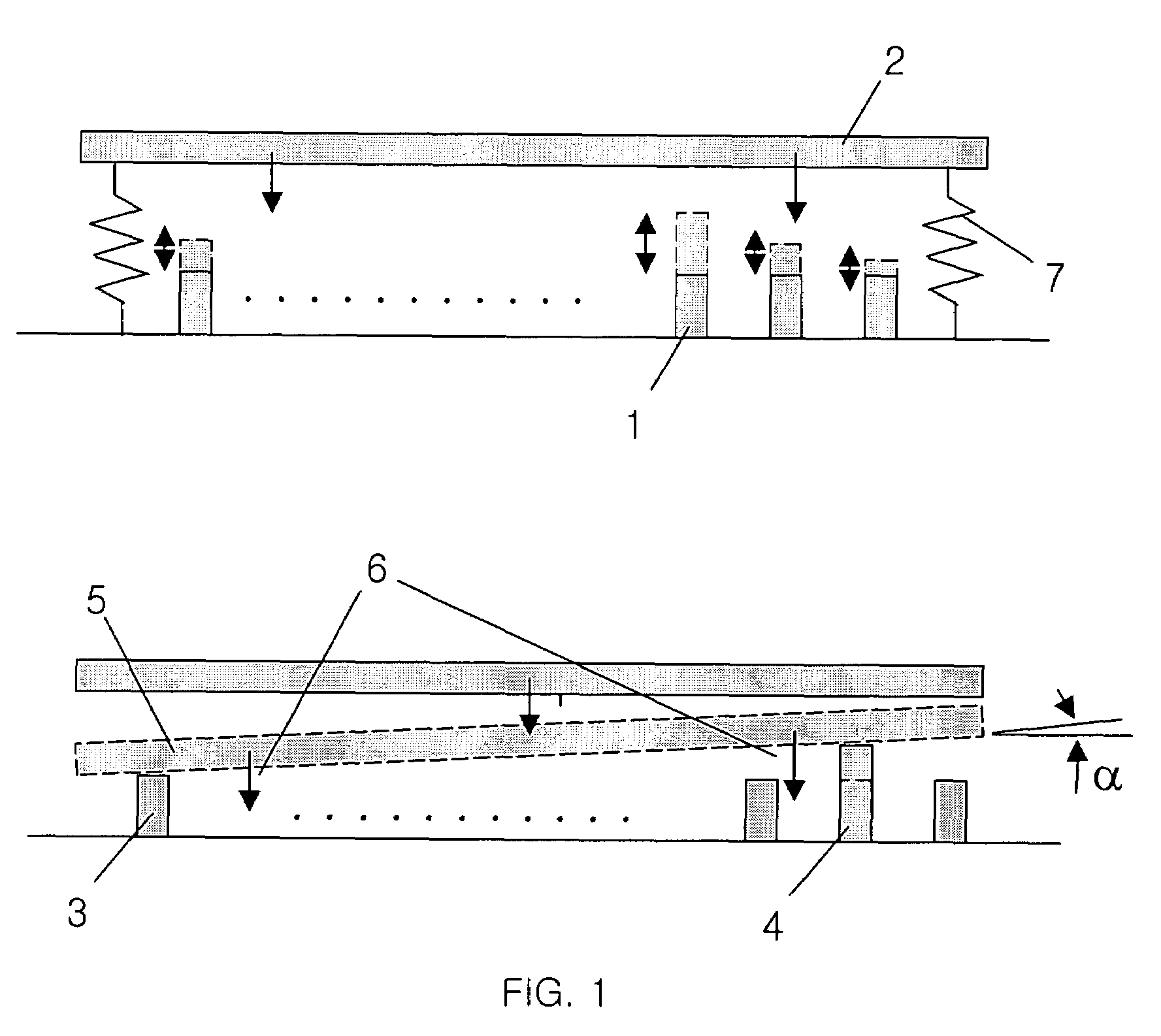
[0034]FIG. 1 shows the concept of the DCM with the variable supports 1. The variably supported discretely controlled micromirror (VSDCM) uses supports 1 providing gaps of various width through which the micromirror can move. The supports 1 are located under the micromirror 2. Translation and rotation of the VSDCM are determined by combinations of gaps, which are determined by variable supports 3, 4 on which the micromirror 5 rests. Gaps determined by the variable supports are controlled and the micromirror rests on the controlled supports 3, 4 by attractive force 6. Therefore, the combination of gaps which the supports 3, 4 provide determines translation and rotation of the micromirror 2. Gap variation by the supports 3, 4 is determined by bistable motions of the supports 3, 4 and the motions are controlled by digital voltage. The position of micromirror 5 is restored to its initial position by the force of flexible spring 7 when the attractive force is off.

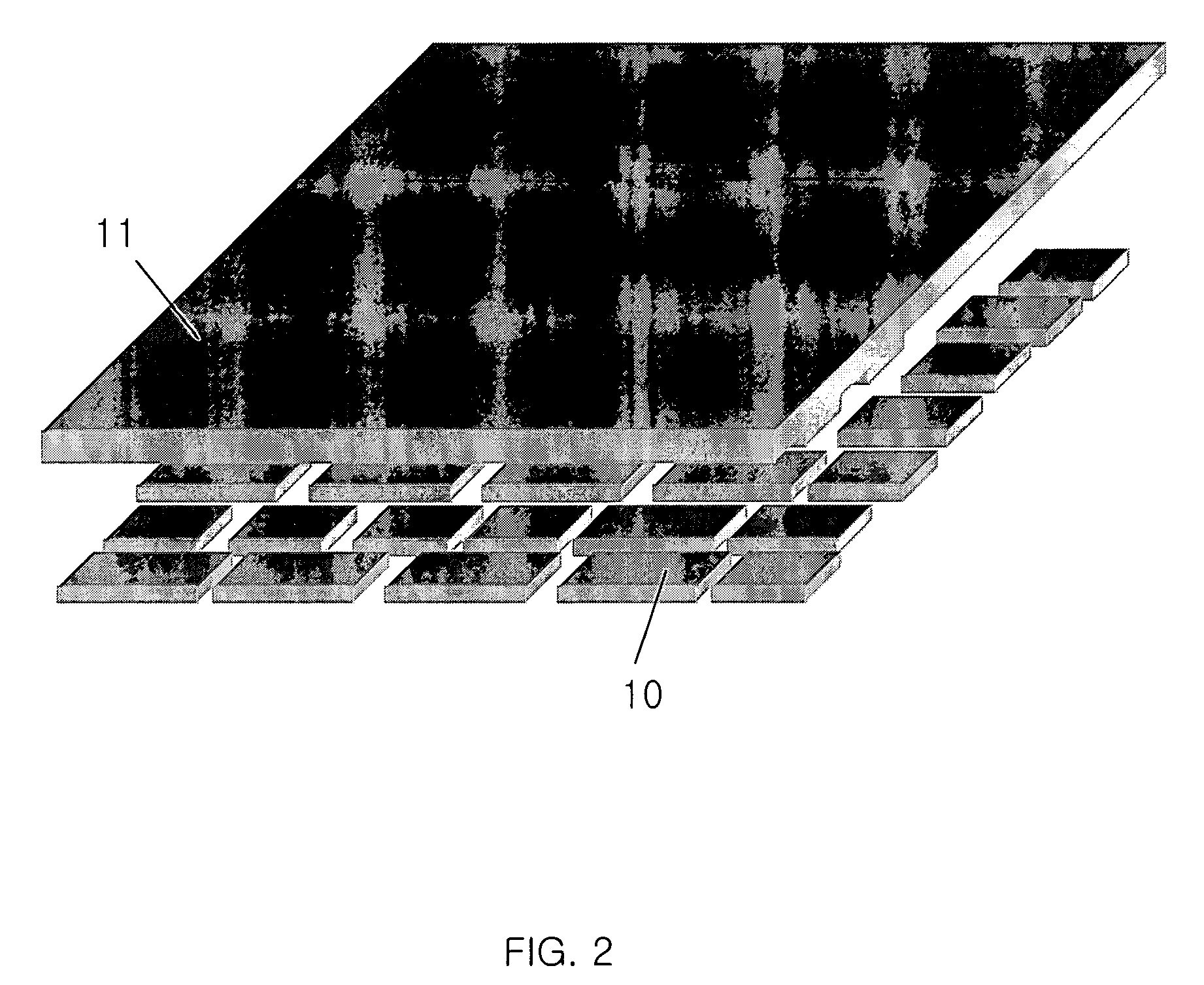
[0035]FIG. 2 shows anothe...


PUM


Abstract

A discretely controlled micromirror array lens (DCMAL) consists of many discretely controlled micromirrors (DCMs) and actuating components. The actuating components control the positions of DCMs electrostatically. The optical efficiency of the DCMAL is increased by locating a mechanical structure upholding DCMs and the actuating components under DCMs to increase an effective reflective area. The known microelectronics technologies can remove the loss in effective reflective area due to electrode pads and wires. The lens can correct aberrations by controlling DCMs independently. Independent control of each DCM is possible by known microelectronics technologies. The DCM array can also form a lens with arbitrary shape and / or size, or a lens array comprising the lenses with arbitrary shape and / or size.

Description

BACKGROUND OF THE INVENTION[0001]The present invention relates to a variable focal length lens consisting of a discretely controlled micromirror (DCM) array and operational methods for controlling the DCM array.[0002]A widely used conventional variable focal length system makes use of two refractive lenses. It has complex driving mechanisms to control the relative positions of the refractive lenses. This conventional system also has a slow response time. Alternatively, variable focal length lenses can be made by changing the shape of the lens, as is done in the human eye. This method has been used in lenses made with isotropic liquids. Other lenses have been made of media with an electrically variable refractive index to create either a conventional lens or a gradient index lens by means of a voltage gradient. The electrically variable refractive index allows the focal length of the lenses to be voltage controlled. Among them, the most advanced variable focal length lens is a liquid...

Claims


Application Information

Patent Timeline
Patent Type & Authority Patents(United States)
IPC IPC(8): G02B26/00G02B5/08G02B7/182
CPCG02B3/14G02B5/09G02B26/0825G02B26/0841G02B26/0866G02B26/08G02B26/00
Inventor CHO, GYOUNG ILSEO, CHEONG SOOKIM, TAE HYEONGIM, DONG WOO
Owner STEREO DISPLAY
Why Eureka
Try Eureka