Efficient laser drilling and cleaning optical system

A laser drilling and optical system technology, applied in the field of laser scanning, can solve the problems of restricting the efficiency of laser drilling and laser cleaning, and achieve the effect of improving the effective reflection area, reducing the quality, and overcoming the large and bulky

Pending Publication Date: 2018-12-14
浙江君华镭弘新材料有限公司
View PDF7 Cites 3 Cited by
  • Summary
  • Abstract
  • Description
  • Claims
  • Application Information

AI Technical Summary

Problems solved by technology

However, since the current laser drilling and laser cleaning mainly use the galvanometer to realize the two-dimensional scanning of the beam, it is limited by the maximum working angular velocity of the galvanometer. Taking the field mirror with a focal length of 650mm as an example, the current maximum scanning speed can only reach 10m / min, restricting the efficiency of laser drilling and laser cleaning

Method used


Image

  • Efficient laser drilling and cleaning optical system
  • Efficient laser drilling and cleaning optical system

Examples


Embodiment 1

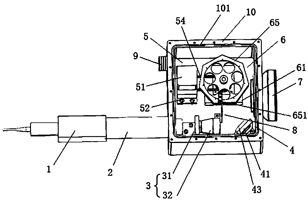
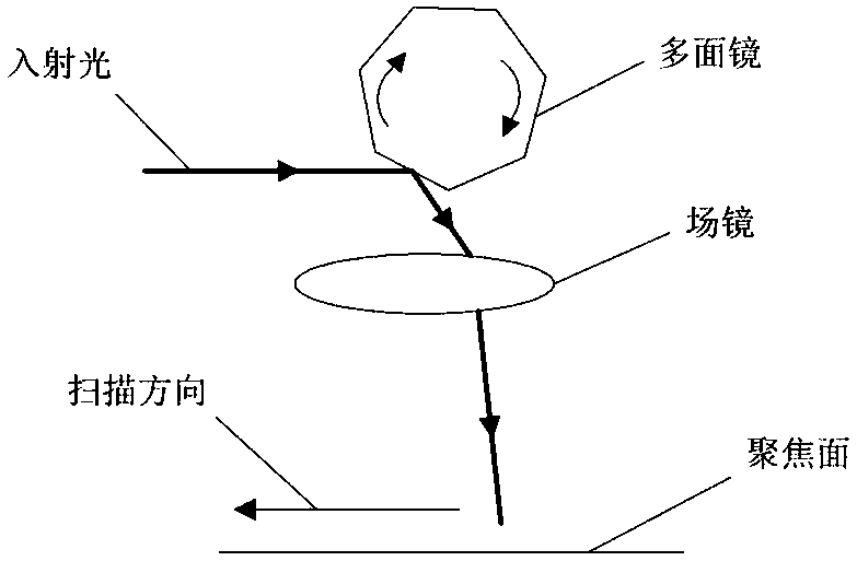
[0025] A high-efficiency laser drilling and cleaning optical system, comprising a housing 10, an upper cover, an optical fiber collimator coupler 1 arranged outside the housing 10, a coupler flange 2, a field lens assembly 7, an electrical connector 9, and a device Beam expander assembly 3, reflector assembly 4, polygon mirror assembly 6, motor assembly 5, photoelectric switch assembly 8 in described shell 10; Described optical fiber collimating coupler 1 is connected to by described coupler flange 2 On the side of the housing 10, the beam expander assembly 3 is arranged in the laser incident direction of the fiber collimator coupler 1, and the reflector assembly 4 is arranged in the laser incident direction of the beam expander assembly 3 , and reflect the laser light to the polygon mirror assembly 6; the motor assembly 5 is connected to the polygon mirror assembly 6 to drive the rotation of the polygon mirror assembly 6, and the field lens assembly 7 is arranged on the polygo...

Embodiment 2

[0029] On the basis of Embodiment 1, the beam expander assembly 3 includes a beam expander bracket 31 and a beam expander 32, the beam expander bracket 31 is arranged on the bottom surface of the housing 10, and its upper part is provided with a threaded through hole, The beam expander 32 is connected in the threaded through hole. The structure is convenient for installation, disassembly and maintenance. The main axis of the beam expander 32 coincides with the optical axis of the laser to expand the laser beam so as to obtain a small-diameter spot on the focal plane of the field lens.

[0030] The reflector assembly 4 includes a reflector bracket 41, a reflector and a mirror pressure ring 43. The reflector bracket 41 is arranged on the bottom surface of the housing 10, and its upper part is provided with a counterbore, and the inner side wall of the counterbore is provided with There is an internal thread, the reflector is arranged in the counterbore, and the outside of the re...


PUM


Abstract

The invention relates to an efficient laser drilling and cleaning optical system, and belongs to the technical field of laser scanning. The efficient laser drilling and cleaning optical system comprises a shell, an upper cover, an optical fiber collimating coupler, a coupler flange, a field lens assembly, an electrical connector, a beam expander assembly, a reflector assembly, a polygonal mirror assembly, a motor assembly and a photoelectric switch assembly, wherein the optical fiber collimating coupler, the coupler flange, the field lens assembly, and the electrical connector are arranged onthe outer side of the shell, and the beam expander assembly, the reflector assembly, the polygonal mirror assembly, the motor assembly and the photoelectric switch assembly are arranged in the shell.The optical fiber collimating coupler is connected to the side face of the shell through the coupler flange, the beam expander assembly is arranged in the laser entering direction of the optical fibercollimating coupler, and the reflector assembly is arranged in the laser entering direction of the beam expander assembly, and reflects lasers to the polygonal mirror assembly. The motor assembly isconnected to the polygonal mirror assembly in a transmitting mode to drive the polygonal mirror assembly to rotate, and the field lens assembly is arranged in the laser reflection direction of the polygonal mirror assembly. According to the efficient laser drilling and cleaning optical system, the speed of laser scanning can be greatly increased, so that the efficiency of laser drilling or laser cleaning is improved.

Description

technical field [0001] The invention relates to the technical field of laser scanning, in particular to an efficient laser drilling and cleaning optical system. Background technique [0002] Since the advent of lasers in the 1960s, laser technology has developed rapidly. Research has been carried out around the application of lasers. With the development of pulsed lasers, the emergence of pulsed lasers with high repetition rate and high peak power has promoted the development of laser drilling and laser cleaning applications. However, since the current laser drilling and laser cleaning mainly use the galvanometer to realize the two-dimensional scanning of the beam, it is limited by the maximum working angular velocity of the galvanometer. Taking the field mirror with a focal length of 650mm as an example, the current maximum scanning speed can only reach 10m / min, restricting the efficiency of laser drilling and laser cleaning. Contents of the invention [0003] The purp...

Claims


Application Information

Patent Timeline
Patent Type & Authority Applications(China)
IPC IPC(8): B23K26/082B23K26/064B23K26/067B23K26/382
CPCB23K26/064B23K26/0643B23K26/067B23K26/0821B23K26/382
Inventor 王炜蔡道叶
Owner 浙江君华镭弘新材料有限公司
Why Eureka
Try Eureka