Dock mounted fish live box

a live box and fish technology, applied in the field of fish live boxes, can solve the problems of fish dying quickly in these live wells

Inactive Publication Date: 2012-08-14
LUECK DOUGLAS A
View PDF37 Cites 5 Cited by
  • Summary
  • Abstract
  • Description
  • Claims
  • Application Information

AI Technical Summary

Problems solved by technology

Fish die quickly in these live wells because the aeration systems pull in warm surface water.

Method used


Image

  • Dock mounted fish live box
  • Dock mounted fish live box
  • Dock mounted fish live box

Examples


Embodiment Construction

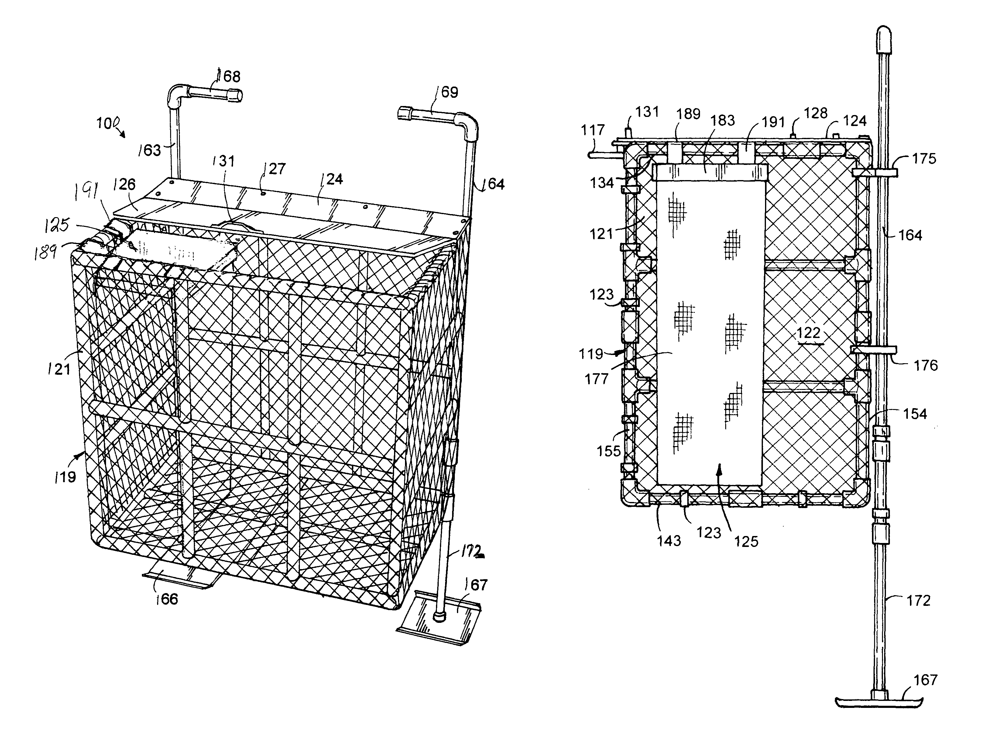
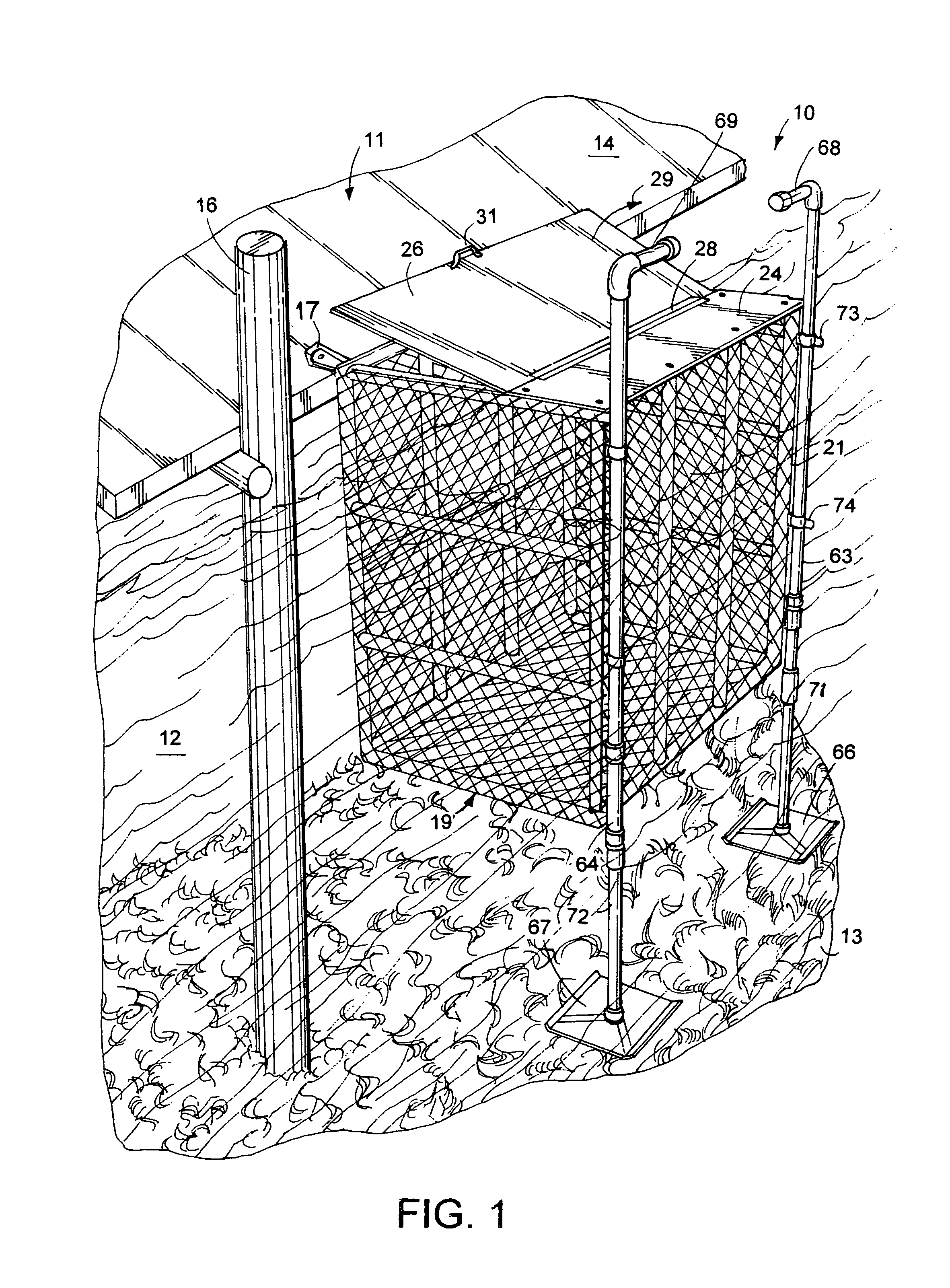
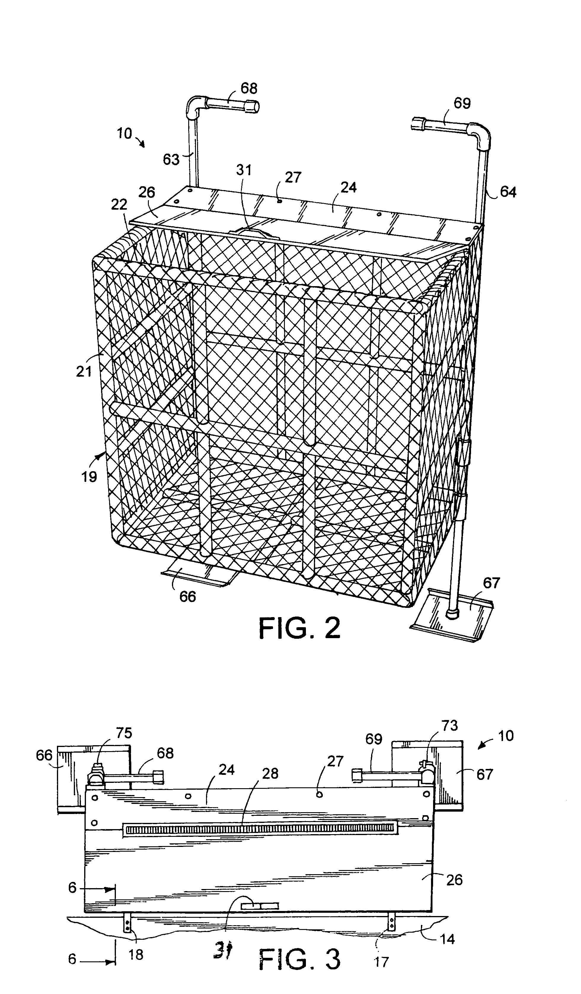
[0022]A fish live box 10 of the invention mounted on the side of a dock 11, shown in FIG. 1, extends downward into a body of water 12, such as a lake, pond or river, to retain fish in the water. Dock 11 is a conventional structure having a horizontal deck 14 extended over the surface of water 12 and anchored to the bottom or bed 13 of the body of water with upright posts 16. Other devices such as floats, can be used to support deck 14 on water 12. A pair of brackets 17 and 18 connect fish live box 10 to a side of deck 14. Fish live box 10 can be removed from brackets 17 and 18 to allow box 10 to be raised out of the water and placed in a storage location. Box 10 is not broken down or taken apart when it is removed from dock 11.

[0023]Bracket 17, shown in FIGS. 6 and 7, is a hook shaped member having a flat base 82 secured with fasteners 83 and 84 to deck 14, A lip 86 joined to base 82 extends around a top frame member 33 of box 10. A removable pin 87 extends through a hole in base 82...


PUM


Abstract

A fish live box has a frame assembly supporting a mesh screen surrounding a chamber for accommodating fish. A minnow cage is located in the chamber. A top wall and door closes the top of the frame assembly. Brackets mount the fish live box to a dock. Upright legs mounted on the frame assembly are vertically adjustable to locate pads on the bottom of the legs on the bed of a body of water to support the fish live box on the bottom of a body of water.

Description

CROSS REFERENCE TO RELATED APPLICATION[0001]This application is a continuation-in-part of U.S. patent application Ser. No. 11 / 455,543 filed Jun. 19, 2006, now U.S. Pat. No. 7,562,491. Application Ser. No. 11 / 455,543 claims the priority benefit of U.S. Provisional Application Ser. No. 60 / 595,293 filed Jun. 21, 2005.FIELD OF THE INVENTION[0002]The invention relates to aquatic vertebrate and living matter holding structures. The holding structures comprise boxes connected to docks for holding live fish in a body of water.BACKGROUND OF THE INVENTION[0003]Floating fish baskets and live wells are used for fish caught alive for an extended period of time. Floating fish baskets have buoyant rings attached to nets to form holding areas for fish. Tether lines are used to secure the basket to a boat or dock. Examples of floating fish baskets are disclosed in U.S. Pat. Nos. 3,478,463; 3,919,803; D462,737; and D485,329. These fish baskets are portable structures that float on the surface of a bo...

Claims


Application Information

Patent Timeline
Patent Type & Authority Patents(United States)
IPC IPC(8): A01K97/20A01K97/05A01K97/04
CPCA01K97/05A01K97/20
Inventor LUECK, DOUGLAS A.
Owner LUECK DOUGLAS A
Why Eureka
Try Eureka