In-wheel suspension system with remote spring and damper means

a suspension system and remote spring technology, applied in the direction of suspensions, steering parts, vehicle components, etc., can solve the problems of limited overall system motion, significant complexity, and numerous inherent limitations of conventional articulating linkages described above, so as to overcome the disadvantages of geometry and friction, and eliminate articulating linkages

Active Publication Date: 2012-08-14
MULTIMATIC INC
View PDF10 Cites 7 Cited by
  • Summary
  • Abstract
  • Description
  • Claims
  • Application Information

AI Technical Summary

Benefits of technology

[0013]Accordingly, it would be advantageous to create a suspension system that provides all the advantages of the in-wheel arrangements described in the prior art but without the inherent disadvantages of their inadequate spring and damping configurations and associated deficient steering geometries. An object of the present invention, therefore, is to provide a suspension system that eliminates the articulating linkages of conventional arrangements by packaging the motion control aspect within the vehicle's wheel volume envelope. It would be a significant improvement over the prior art to integrate an adequately sized spring and damper arrangement packaged in such a way as not to impart undesirable loads on the system. Another major advantage would be realized if a steering arrangement was provided that overcame the geometry and friction disadvantages of previous in-wheel suspension systems.
[0014]The present invention provides a suspension system for vehicles that comprises an upright that includes a spindle configured to carry a wheel bearing assembly. The bearing assembly is adapted to provide a rotatable mounting for a wheel hub. The wheel hub is provided with a detachable connection for a wheel and tire assembly. The upright also includes a mounting flange for a brake caliper and a fastening means. A strut shaft is rigidly attached to the upright via the fastening means and includes a pumping piston and piston seal. A main housing is configured with a bearing arrangement adapted to guide and support the strut shaft, a sealing system to contain a pumping fluid, a mounting arrangement for attachment to the main vehicle structure and a fluid port. A remote suspension module is configured with a hydraulic actuation piston, an energy storage device and a damping device. The fluid port of the main housing is connected to the hydraulic actuation piston of the remote suspension module via a hydraulic connection so that when the pumping piston of the strut shaft moves within the main housing, the motion is directly transmitted to the hydraulic actuation piston via the pumping fluid. The vehicle's suspension movement is essentially defined as the motion of the wheel and this is constrained to a predetermined path by the guidance of the strut shaft via the bearing arrangement. The predetermined suspension movement is then transmitted to the energy storage device and damping device of the remote suspension module via the pumping fluid. In this way the energy storage device and damping device can be located remotely from the upright, strut shaft and main housing which allows these components to be easily contained within the volume of the wheel. This also allows the entire suspension motion to be contained within the wheel volume thereby liberating a significant amount of the vehicle volume for alternative use as well as eliminating the need for articulating links and their associated structural mounting points.
[0015]In a further aspect of the present invention, the main housing is provided with a steering bearing adapted to rotatably mount a steering arm to the main housing in coaxial alignment with the strut shaft. A guide shaft is rigidly attached to the upright in parallel alignment with the strut shaft. The steering arm is configured with a rotational mounting joint for attachment to the steering bearing, a tie rod attachment and a guide joint adapted to translate along the guide shaft. The tie rod end of a typical vehicle steering linkage is connected to the tie rod attachment so that steering motion is translated into rotational motion of the upright and strut shaft around the strut shaft axis. The steering motion is imparted on the upright via the steering arm guide joint acting on the guide shaft. The vehicle's suspension movement is decoupled from the steering arm via the translation of the guide joint along the guide shaft. In this way toe-steer, or bump-steer, is completely eliminated.

Problems solved by technology

A combination of independent links and appropriately restrained connection joints results in an overall system motion that is generally limited to being fully controlled by the spring and damper.
All of the conventional articulated linkages described above possess numerous inherent limitations that include significant complexity, the requirement for substantial and extensive vehicle structure for mounting, considerable cost and a requirement for large packaging volumes to contain their motion.
Although this prior art embodiment describes a novel approach to simplifying the suspension system of a vehicle, it does not provide any method of damping the spring motion.
Additionally, detailed calculation and a study of existing road vehicle suspension springs illustrate that the spring size and package suggested in U.S. Pat. No. 3,578,354 are unrealistically small.
A correctly sized spring would not be capable of fitting in the space provided by this prior art configuration.
This large offset would introduce highly undesirable torque loads to the guide member resulting in friction within the suspension movement that is known by those skilled in the art to seriously degrade performance.
Although this prior art embodiment describes an assembly that allows all the essential function of the suspension to be integrated into the actual interior of the volume within the wheel with a realistic spring package and a method for eliminating bump-steer, it does not provide a conventional damper to control the oscillatory nature of the spring-mass system.
U.S. Pat. No. 6,113,119 makes reference to electromechanical means to control the deflecting movements of the wheel as an alternative to the spring and damper, but as this method has no current application in the industry, the lack of inclusion of a conventional damper is a significant limitation of this prior art arrangement.
Both the steering arrangement and spring position would impart significant frictional loads in the suspension movement which is highly undesirable.
However, once again, detailed calculation and a study of existing road vehicle suspension springs illustrate that the spring and damper size suggested in U.S. Pat. No. 6,357,770 are unrealistically small.
The configuration would not be suitable for general purpose road going vehicles due to the light duty nature of the inter-engaging sliding mount assembly and the small size of the spring mechanism and damping device.
Additionally, this prior art configuration does not describe a methodology for allowing the moving suspension components to be steered which is a significant limitation of this arrangement.

Method used


Image

  • In-wheel suspension system with remote spring and damper means
  • In-wheel suspension system with remote spring and damper means
  • In-wheel suspension system with remote spring and damper means

Examples


Embodiment Construction

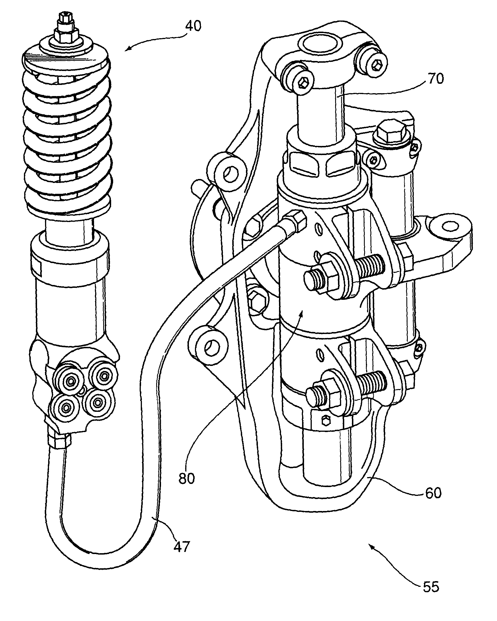
[0039]Referring to FIG. 5, a suspension system (55) is substantially constructed from an upright (60), a strut shaft (70), a main housing (80) and a remote suspension module (40). Referring to FIGS. 6 and 8, the upright (60) is configured with a spindle (61), a mounting flange (62) for a brake caliper (105) and a fastening means (63). The spindle (61) is configured to carry a wheel bearing assembly (64) which is adapted for rotatable mounting of a wheel hub (65). The wheel hub (65) additionally includes a detachable connection (66) for a wheel (100) and tire (101) assembly. Referring to FIGS. 7 and 10, the main housing (80) is substantially constructed from a pressure tube (86) a pair of removable seal caps (82) and a mounting arrangement (81) for attachment to a main vehicle structure. The seal caps (82) contain a sealing system (83), and a threaded retention aspect (85) configured to interact with a matching pressure tube thread (87), and are adapted to retain a bearing arrangemen...


PUM


Abstract

A vehicle suspension system (55) is configured so as to contain all of the suspension motion control elements completely within the volume of the road wheel (100) while remotely locating the energy storage device (45) and damping device (42). An upright (60) comprises the spindle (61), brake caliper (105), and structure to hold a main strut shaft (70) parallel to a secondary strut shaft (67). The suspension's motion is controlled by the shafts which slide relative to the sprung part of the vehicle (1). The main strut shaft (70) includes a pumping piston (73). The fluid (91) displaced by the pumping piston (73) flows through a hydraulic connection (47) to a remote suspension module (40) mounted to the sprung part of the vehicle. The remote suspension module (40) hydraulically transmits the wheel motion to the remote energy storage device (45) and damping device (42). A steering arm (95) rotating around the main strut shaft (70) is configured to allow both struts (70 and 67) to slide through it, thus eliminating bump steer.

Description

RELATED APPLICATIONS[0001]This application is a 35 U.S.C. 371 national stage filing from International Application No. PCT / CA2008 / 001856 filed Oct. 21, 2008, which claims priority to Canadian Patent Application No. 2,608,825, filed Oct. 26, 2007, the teachings of which are incorporated herein by reference.FIELD OF THE INVENTION[0002]This invention relates to a suspension system for wheeled vehicles.BACKGROUND OF THE INVENTION[0003]The suspension system of a vehicle is primarily provided to isolate the occupant compartment from road irregularities. However, suspension also plays an important role in reducing the amount of energy expended as the vehicle encounters bumps in its path. The most common approach to vehicle suspension is to provide an articulating linkage that allows the tire, wheel, brake assembly, bearing arrangement and associated structural member to move independently, but in a predetermined manner relative to the main vehicle structure. The subassembly of tire, wheel,...

Claims


Application Information

Patent Timeline
Patent Type & Authority Patents(United States)
IPC IPC(8): B60G3/01
CPCB60G3/01B60G11/006B60G15/067B60G17/0272B62D7/18B60G2204/12B60G2204/4232B60G2204/8304B60G2206/50B60G2500/30B60G2204/30
Inventor HOLT, LAURENCE JSPARROW, THOMAS ALEXANDER
Owner MULTIMATIC INC
Why Eureka
Try Eureka