Remotely controllable track lighting system

a remote control and track technology, applied in lighting and heating apparatus, instruments, lighting support devices, etc., can solve the problems of many aspects still limited

Active Publication Date: 2012-09-04
3336820 NOVA SCOTIA LTD +1
View PDF28 Cites 15 Cited by
  • Summary
  • Abstract
  • Description
  • Claims
  • Application Information

AI Technical Summary

Benefits of technology

[0009]As an optional feature of the present invention, depressing the pre-set level button multiple times in succession causes all of the lamps to be set to a maximum intensity level.
[0011]As a further aspect of the present invention, the wireless remote includes a “uniform control” button, and depressing this button causes the controller to set all of the lamps to a uniform intensity level. Depressing the uniform control button multiple times causes all of the lamps to cycle through different intensity levels.
[0012]As an additional aspect of the present invention, the track light system may be powered via a switch, such as a wall switch, wherein moving the switch from the off position to the on position causes each of the lamps on the track to be set to their respective previously set intensity level. As an optional feature, moving the switch from the on position, then to the off position, and back to the on position, within a short period of time causes all of the lamps to be set to the maximum intensity level.

Problems solved by technology

Although existing track lighting systems provide some flexibility (e.g. lamps can be rotated), they are still limited in many respects.

Method used


Image

  • Remotely controllable track lighting system
  • Remotely controllable track lighting system
  • Remotely controllable track lighting system

Examples


Embodiment Construction

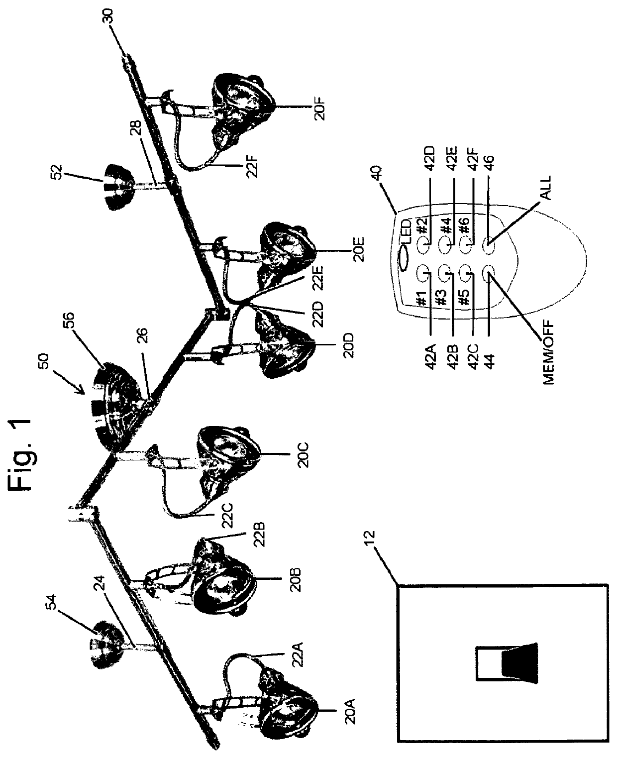
[0022]The present invention relates to improvements in track lighting. The remotely controllable track lighting system (or, for convenience, “track lighting system”) of the present invention entails track lighting that is controllable in various novel manners by a wireless remote control and a central controller with or without a wall-mounted switch. As discussed in detail below, the track lighting system of the present invention is designed to enable the individual lamps (or “lights”) within the system to be individually controlled so that different lamps can be set to different intensity levels and, further, the lamps can be quickly and easily set to previously set intensity levels. Other features of the track lighting system also are described.

[0023]FIG. 1 of the accompanying drawings schematically illustrates the remotely controllable track lighting system 10 (“track lighting system 10” or “system 10”) of the present invention. As shown, track lighting system 10 includes multipl...


PUM


Abstract

A remotely controllable track lighting system includes a track mountable to a support structure, such as a wall or ceiling, with lamps that are supported on the track that are individually controlled by a wireless remote. Each lamp on the track may be set to respectively different intensity levels (e.g., high, mid, low, off) or the user can uniformly control the lamps to be set to the same intensity level. Advantageously, all of the lamps may be set, upon initially turning on the lamps or at another time as desired, to their respective previously set intensity levels. The track system may also be powered via a wall switch where initially turning on the lamps via the wall switch advantageously causes all of the lamps to return to their respective previously set intensity levels or the user can move the wall switch off then on within a short period of time (e.g., 3 seconds) to cause all of the lamps to be set high. Other features and variations also are provided.

Description

REFERENCE TO RELATED APPLICATION[0001]This application claims priority to U.S. provisional application No. 61 / 097,404, filed Sep. 16, 2008, the disclosure of which is incorporated herein by reference.FIELD OF THE INVENTION[0002]The present invention relates to a remotely controllable track lighting system providing wireless remote control of individual lamps within the track lighting system through a central main control unit.BACKGROUND OF THE INVENTION[0003]Track lighting systems are very popular and easy to install. Generally, they include multiple lamps supported on a track that itself is mounted to a support structure such as a ceiling or a wall. The lamps may be fixed or positioned at any point along the full length of the track, and the angle of each lamp also may be adjusted in either case. The lamps are powered from a single power supply whose power is distributed by conductors running along the inner surfaces of the track. Lamps and tracks are available in a variety of deco...

Claims


Application Information

Patent Timeline
Patent Type & Authority Patents(United States)
IPC IPC(8): H05B37/02H05B39/00F21V21/34
CPCH05B37/029H05B37/0272F21V21/15F21V21/34F21V23/0435H05B47/155H05B47/19F21S2/005F21V21/35
Inventor MEYER, A. CORYDON
Owner 3336820 NOVA SCOTIA LTD
Why Eureka
Try Eureka