
Track lighting fixture

a lighting fixture and track technology, applied in the field of track lighting fixtures, can solve the problems of inability to properly illuminate, limited illumination area of conventional lighting fixtures, and adversely affecting the illumination

Inactive Publication Date: 2015-07-02
DIODE ON OPTOELECTRONICS
View PDF3 Cites 13 Cited by
  • Summary
  • Abstract
  • Description
  • Claims
  • Application Information

AI Technical Summary

Benefits of technology

The present invention is a track lighting fixture that can adjust the direction and range of its illumination, resulting in a more condensed and directed beam of light.

Problems solved by technology

However, range and orientation of illumination area of the conventional lighting fixture are limited by its mounting position.
For example, when the article disposed in the display cabinet has a different size or is placed at a different position, it cannot be illuminated properly due to the limited range and orientation of the illumination area attributed to the position of the conventional lighting fixture.
Further, light emitted from the conventional lighting fixture usually diffuses, which adversely affects the illumination effect.

Method used


Image

  • Track lighting fixture
  • Track lighting fixture
  • Track lighting fixture

Examples


Embodiment Construction

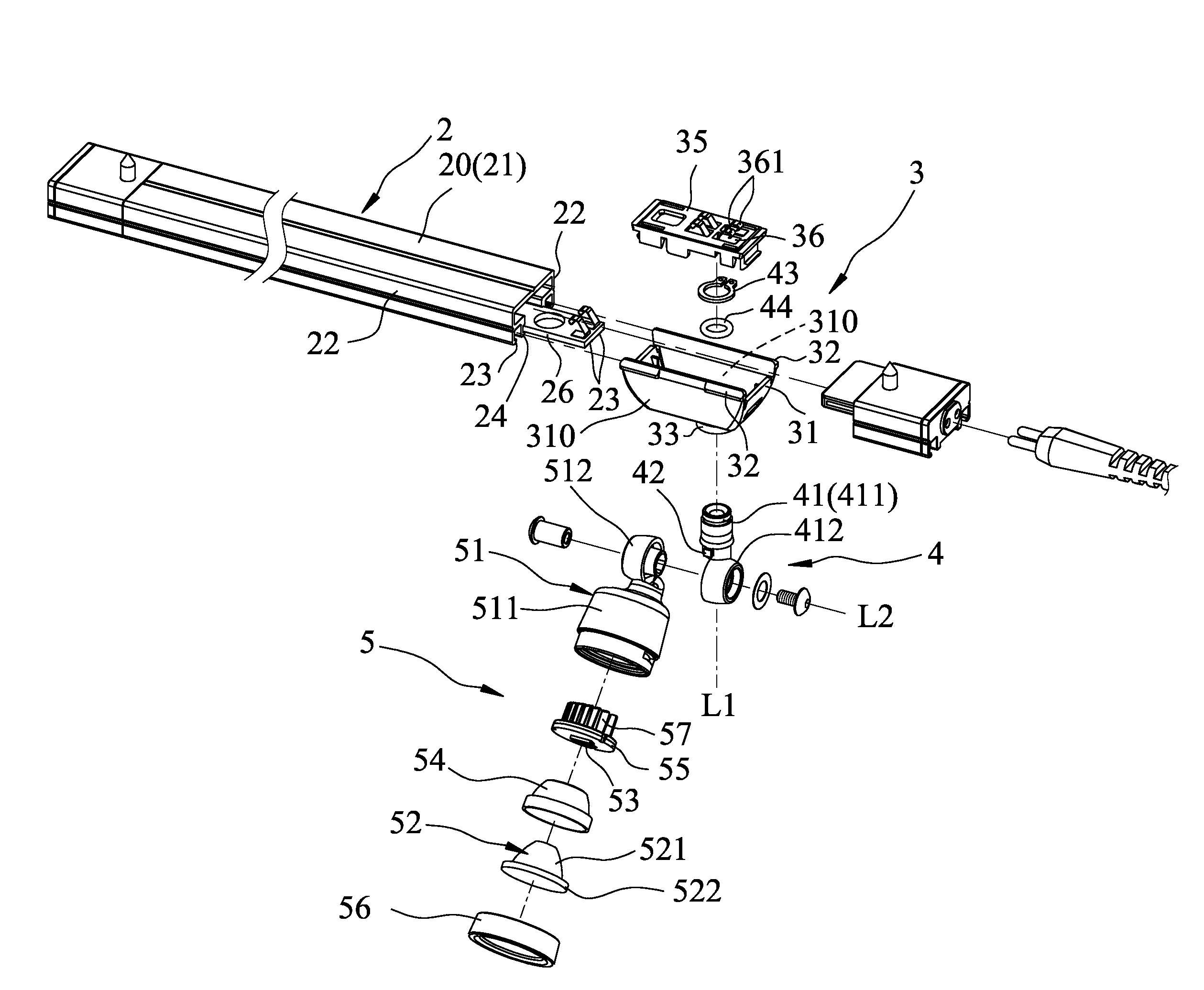
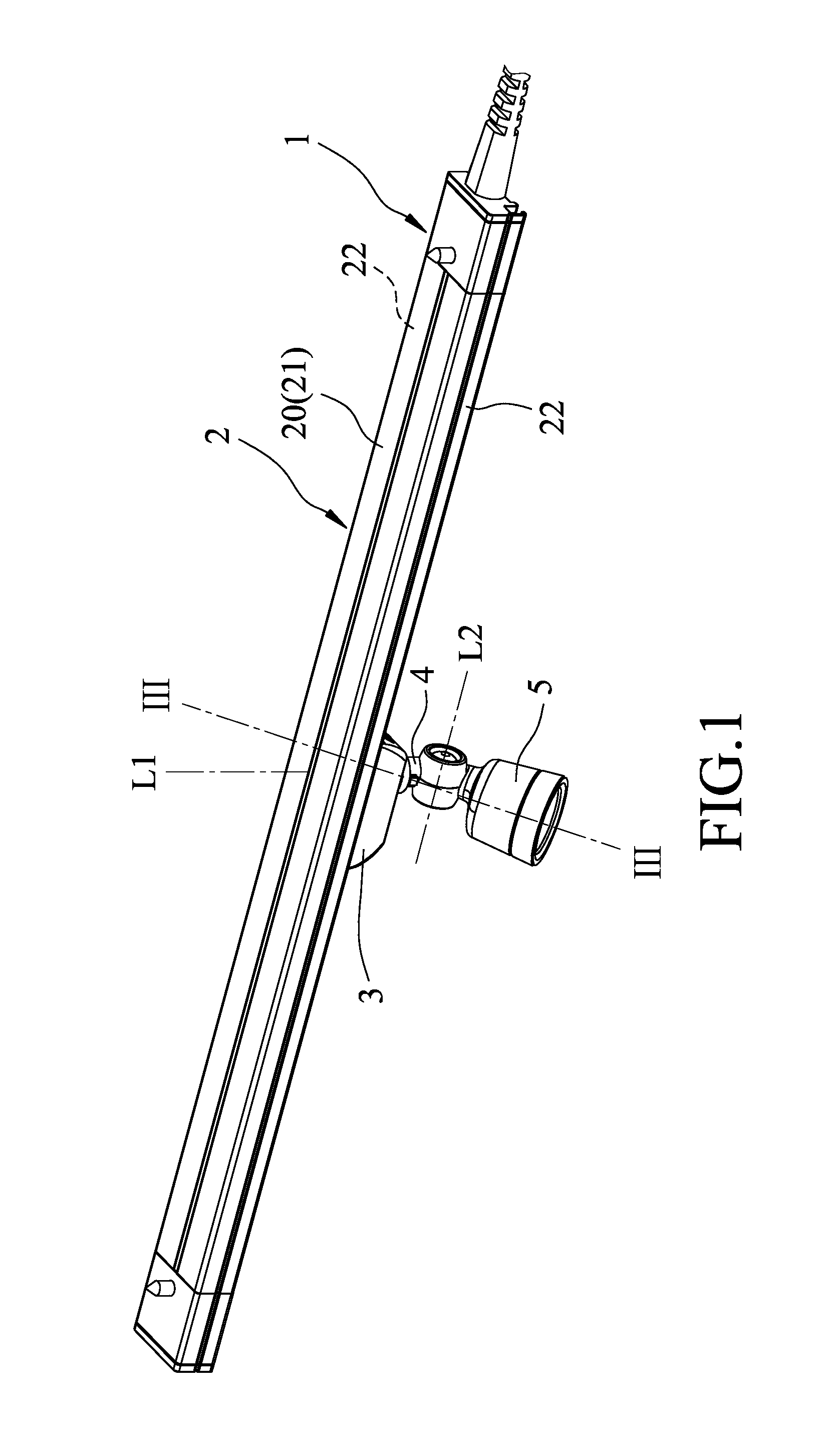
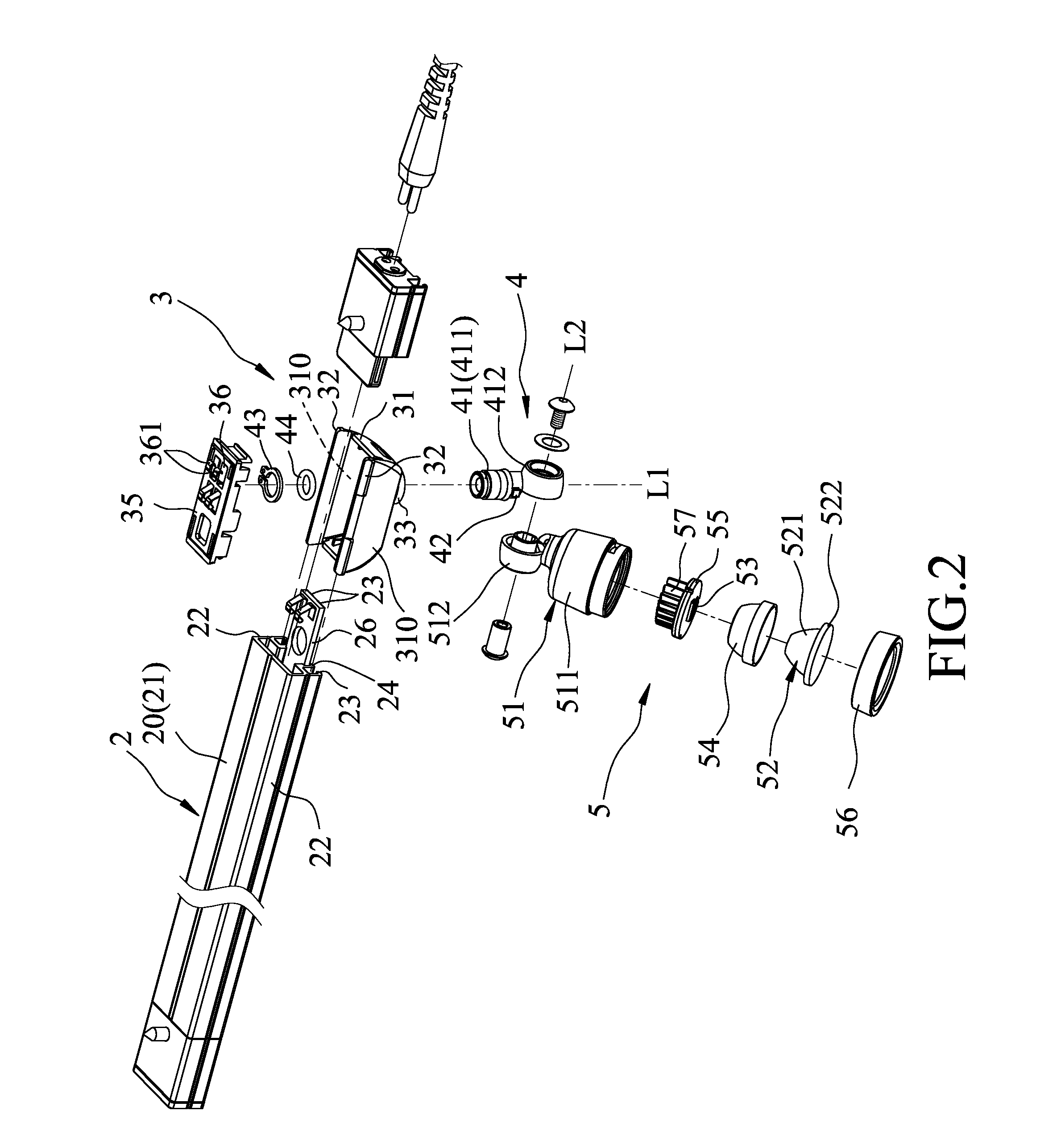
[0016]Referring to FIGS. 1 to 4, the preferred embodiment of the track lighting fixture 1 according to the present invention is shown to include a rail unit 2, a slidable module 3, a rotatable module 4, and a lighting device 5.

[0017]The rail unit 2 includes a rail 20 and a power supply circuit board 26. The rail 20 includes a top wall 21, two side walls 22, two guiding flanges 23, and two mounting protrusions 24. The side walls 22 extend respectively and downwardly from opposite sides of the top wall 21. Each of the guiding flanges 23 extends from a lowermost end of a respective one of the side walls 22 toward the other one of the side walls 22. The mounting protrusions 24 extend inwardly and respectively from the side walls 22 toward each other for mounting of the power supply circuit board 26. The power supply circuit board 26 is suspended on the mounting protrusions 24, and has a bottom surface 260 provided with a pair of elongated electrodes 261 (see FIG. 4). The electrodes 261 ...


PUM


Abstract

A track lighting fixture includes a rail unit, a slidable module, a rotatable module, and a lighting device. The slidable module is mounted on and is movable along the rail unit. The rotatable module is rotatably mounted to the slidable module and is rotatable about a rotation axis perpendicular to the rail unit. The lighting device is pivotably mounted to the rotatable module, is pivotable about a pivot axis that is perpendicular to the rotation axis, and includes a shade and at least one lighting element. The shade is pivotably mounted to the rotatable module, and the lighting element is disposed in the shade.

Description

BACKGROUND OF THE INVENTION[0001]1. Field of the Invention[0002]The invention relates to a lighting fixture, more particularly to a track lighting fixture.[0003]2. Description of the Related Art[0004]A conventional lighting fixture is usually mounted at four corners of a display cabinet to illuminate an article disposed in the display cabinet. However, range and orientation of illumination area of the conventional lighting fixture are limited by its mounting position. For example, when the article disposed in the display cabinet has a different size or is placed at a different position, it cannot be illuminated properly due to the limited range and orientation of the illumination area attributed to the position of the conventional lighting fixture. Further, light emitted from the conventional lighting fixture usually diffuses, which adversely affects the illumination effect.SUMMARY OF THE INVENTION[0005]The object of the present invention is to provide a track lighting fixture capab...

Claims


Application Information

Patent Timeline
IPC IPC(8): F21V21/34F21V29/00F21S8/00
CPCF21V21/34F21Y2101/02F21V29/2206F21S8/038F21V21/30F21V29/74F21Y2115/10
Inventor LIU, IVAN
Owner DIODE ON OPTOELECTRONICS
Learn More