Differential circuit with precisely controlled terminator circuit

a technology of terminator circuit and differential circuit, which is applied in the direction of logic circuit coupling/interface arrangement, logic system details, pulse technique, etc., can solve the problems of inaccurate termination resistance degradation, and achieve the effect of improving the preciseness of termination resistan

Active Publication Date: 2008-10-02
SUMITOMO ELECTRIC IND LTD
View PDF16 Cites 4 Cited by
  • Summary
  • Abstract
  • Description
  • Claims
  • Application Information

AI Technical Summary

Benefits of technology

[0008]In the termination circuit of the invention, the first transistor operates as a termination resistor for the first input terminal, the second transistor operates as a termination resistor for the second input terminal, and the first and second resistors operates as a termination resistor between the first and second input terminals. Moreover, the voltage of the medium node is determined by the current from the current source multiplied by the equivalent resistance of two transistors, which are connected in parallel between the medium node and the first bias supply, and the control unit adjusts the voltage of the medium node so as to be equal to the reference voltage. Thus, the control unit equivalently adjusts the equivalent resistance of the transistors so as to maintain a preset value equal to the termination resistance of respective input terminals, which may precisely control the termination resistance independent of the variation of the resistors and the fluctuation in the power supply.
[0009]The termination circuit of the invention may further include third and fourth resistors each connected between the first transistor and the first input terminal, and between the second transistor and the second input terminal. The termination resistor for the first input terminal includes a series connection of the first transistor and the third resistor, while that for the second input terminal includes the second transistor and the fourth resistor connected in series to the second transistor. According to the configuration above, an adjustable range of the termination resistance solely determined by two transistors may be narrower, which enhances the preciseness of the termination resistance.

Problems solved by technology

Consequently, when the resistance of the transistors, 102b and 103b, or the resistors, 102a and 103a, unbalance by various factors such as the process instability or the inherent temperature dependence of the device, or when the power supply VDD fluctuates, the accuracy of the termination resistance deteriorates.

Method used


Image

  • Differential circuit with precisely controlled terminator circuit
  • Differential circuit with precisely controlled terminator circuit
  • Differential circuit with precisely controlled terminator circuit

Examples


first embodiment

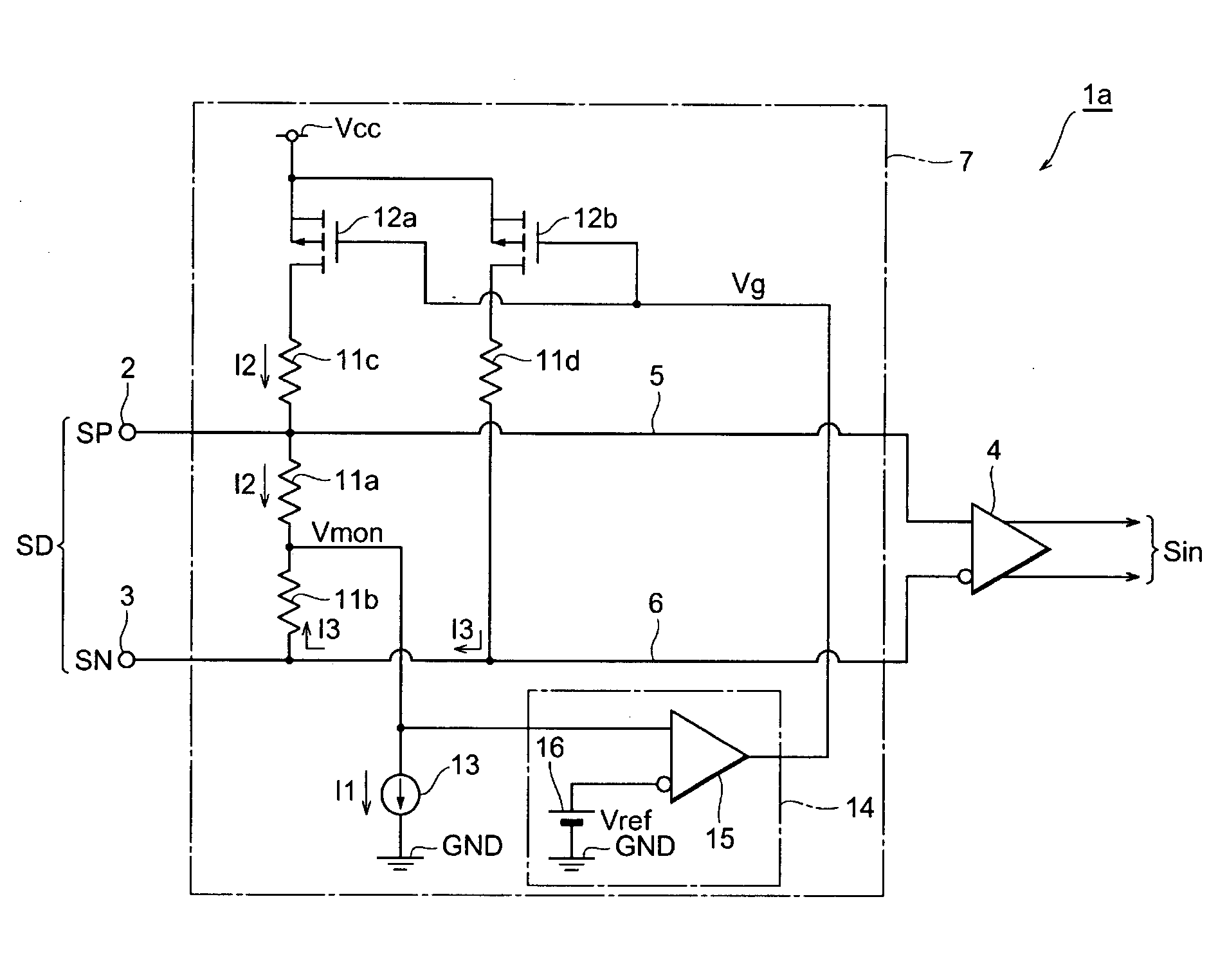
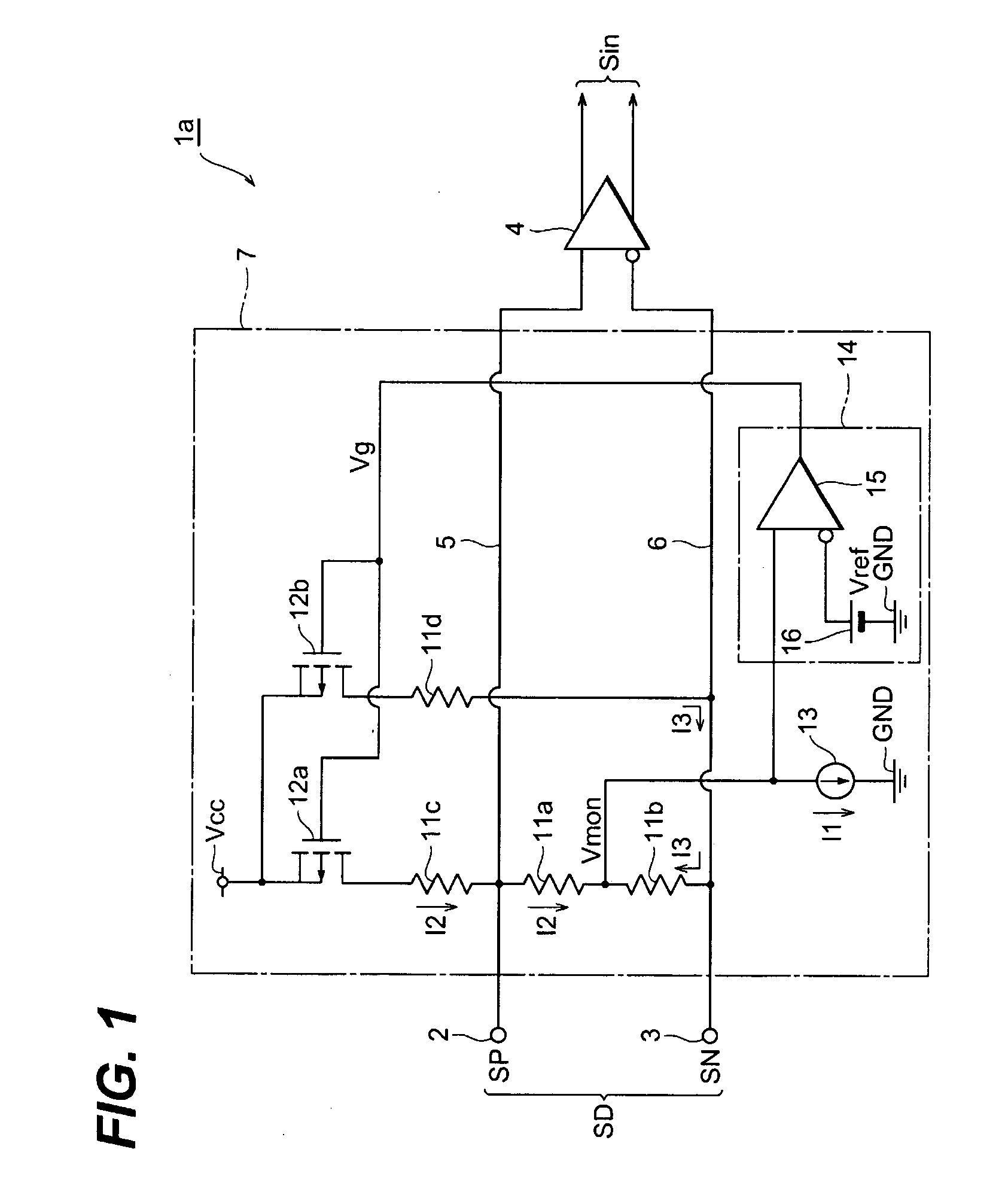
[0016]FIG. 1 shows a circuit diagram of a differential circuit according to the first embodiment of the invention. The differential circuit 1a, which processes the differential signal SD, provides a first terminal 2 to receive the positive phase signal SP of the differential signal SD, a second terminal 2 to receive the negative phase signal SN, an amplifier 4 to amplify the differential signal SD, and a terminator to terminate a signal line 5 to connect the first terminal 2 with the amplifier 4 and another signal line 6 to connect the second terminal 3 with the amplifier 5. The differential circuit 1a shown FIG. 1 is preferable to be integrated within the IC.

[0017]The terminator circuit 7 comprises first to fourth resistors, 11a to 11d, two transistors, 12a and 12b, a current source 13 and a control unit 14. Resistors, 11a to 11d, may be a film resistor integrated within the IC.

[0018]Two resistors, 11a and 11b, are connected in series between the first and second terminals, namely,...

second embodiment

[0037]FIG. 4 is a circuit diagram of a differential circuit 1b according to the second embodiment of the present invention. The circuit 1b provides the first 2 and the second 3 input terminals, the amplifier 4 and the terminator circuit 8. Elements in FIG. 4 except for the terminator circuit 8 are same with those appeared in the first embodiment.

[0038]The terminator circuit 8 includes the first 11a and the second 11b resistors with the same configuration as the first embodiment, and the third 11e and the fourth 11f resistors, two transistors, 12c and 12d, the constant current source 17 and the control unit 18 with a different configuration from those of the first embodiment shown in FIG. 1.

[0039]The transistor 12c, which is the first transistor in the present embodiment, operates as a variable resistor between the first input terminal 2 and the ground GND. That is, the drain of the transistor 12c is connected to the first signal line 5 through the resistor 11e, while, the source the...


PUM


Abstract

The present invention provides a precisely controlled terminator circuit of a differential amplifier, in particular, for a differential amplifier of an optical receiver. The differential circuit, which receives a differential signal by a first input for the normal phase signal and a second input for an anti-phase signal, provides a terminator circuit comprises two resistors connected in serial between two inputs and two resistive connections each including a transistor and a resistor serially connected to the transistor and connected between respective inputs and the power supply line Vcc. The control unit, by receiving a medium potential of two resistors, provides a bias to two transistors so as to equalize the medium potential with the reference potential.

Description

BACKGROUND OF THE INVENTION[0001]1. Field of the Invention[0002]The present invention relates to a differential circuit with a dynamically and precisely controller terminator circuit, in particular, relates to a differential circuit used in an optical receiver.[0003]2. Related Prior Art[0004]Recent high speed communication system requests a termination resistor for an electronic circuit dynamically and precisely controlled. A United States Patent publication 20020145443 has disclosed an example of the termination circuit. FIG. 5 shows a conventional termination circuit 100 disclosed in the publication above, where the circuits 100 terminates the transmission line 101 and includes a resistor unit 102 and a reference unit 103. The resistor unit 102 includes a resistor 102a and an FET 102b connected in serial between the transmission line 101 and the ground. The FET 102b operates as a variable resistor. The reference unit 103 includes a resistor 103a and another FET 103b connected in s...

Claims


Application Information

Patent Timeline
Patent Type & Authority Applications(United States)
IPC IPC(8): H04B10/06H03K19/0175H04B3/02H04L25/02
CPCH03F3/082H03F3/45475H03F2203/45008H03F2203/45138H03F2203/45561H03F2203/45576
Inventor TANAKA, KEIJI
Owner SUMITOMO ELECTRIC IND LTD
Why Eureka
Try Eureka