Optical fiber Bragg grating-based vibrating wire infrasonic wave sensor

A vibrating wire and infrasonic technology, which is used in the measurement of ultrasonic/sonic/infrasonic, instruments, and the use of wave/particle radiation. It can solve the problems of large volume, small frequency range, and low sensitivity.

Inactive Publication Date: 2014-06-18
KUNMING UNIV OF SCI & TECH
View PDF4 Cites 4 Cited by
  • Summary
  • Abstract
  • Description
  • Claims
  • Application Information

AI Technical Summary

Problems solved by technology

[0004] The invention provides a vibrating wire infrasonic sensor based on an optical fiber Bragg grating and its application method, which are used to overcome the shor

Method used


Image

  • Optical fiber Bragg grating-based vibrating wire infrasonic wave sensor
  • Optical fiber Bragg grating-based vibrating wire infrasonic wave sensor
  • Optical fiber Bragg grating-based vibrating wire infrasonic wave sensor

Examples


Embodiment approach 1

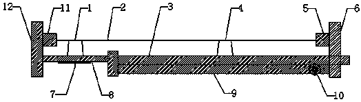
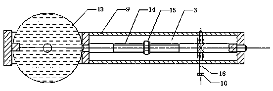
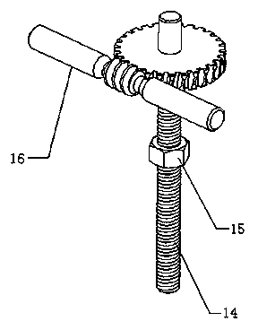
[0072] Implementation mode one: if Figures 1 to 7 As shown, the structure of the vibrating wire infrasonic sensor based on the fiber Bragg grating in this embodiment includes: string horse I1, vibrating wire 2, guide rail 3, string horse II 4 and a fixed bracket, the vibrating wire 2 is suspended and fixed on the fixed bracket, fixed There is an annular part 13 and a right side base plate 9 under the bracket installation vibrating wire 2, the annular part 13 is a circular elastic diaphragm 8, the lower surface of the elastic diaphragm 8 is pasted with a Bragg grating 7, and the right side base plate 9 is installed with a The vibrating string 2 is parallel to the guide rail 3, and the bridge I1 is fixedly installed at the center of the elastic diaphragm 8. The bridge II4 that can move along the guide rail is installed on the guide rail 3, and the vibrating string 2 is in contact with the bridge I1 and the bridge II4. The vibrating string 2 of the fixed support is fixedly conne...

Embodiment approach 2

[0073] Implementation mode two: if Figures 1 to 7 As shown, the structure of the vibrating wire infrasonic sensor based on the fiber Bragg grating in this embodiment includes: string horse I1, vibrating wire 2, guide rail 3, string horse II 4 and a fixed bracket, the vibrating wire 2 is suspended and fixed on the fixed bracket, fixed There is an annular part 13 and a right side base plate 9 under the bracket installation vibrating wire 2, the annular part 13 is a circular elastic diaphragm 8, the lower surface of the elastic diaphragm 8 is pasted with a Bragg grating 7, and the right side base plate 9 is installed with a The vibrating string 2 is parallel to the guide rail 3, and the bridge I1 is fixedly installed at the center of the elastic diaphragm 8. The bridge II4 that can move along the guide rail is installed on the guide rail 3, and the vibrating string 2 is in contact with the bridge I1 and the bridge II4. The vibrating string 2 of the fixed support is fixedly conne...

Embodiment approach 3

[0074] Implementation mode three: if Figures 1 to 7 As shown, the structure of the vibrating wire infrasonic sensor based on the fiber Bragg grating in this embodiment includes: string horse I1, vibrating wire 2, guide rail 3, string horse II 4 and a fixed bracket, the vibrating wire 2 is suspended and fixed on the fixed bracket, fixed There is an annular part 13 and a right side base plate 9 under the bracket installation vibrating wire 2, the annular part 13 is a circular elastic diaphragm 8, the lower surface of the elastic diaphragm 8 is pasted with a Bragg grating 7, and the right side base plate 9 is installed with a The vibrating string 2 is parallel to the guide rail 3, and the bridge I1 is fixedly installed at the center of the elastic diaphragm 8. The bridge II4 that can move along the guide rail is installed on the guide rail 3, and the vibrating string 2 is in contact with the bridge I1 and the bridge II4. The vibrating string 2 of the fixed support is fixedly con...


PUM


Abstract

The invention relates to an optical fiber Bragg grating-based vibrating wire infrasonic wave sensor, belongs to the technical field of an optical measurement device. The structure of the sensor comprises a bridge I, a vibration wire, a guide rail, a bridge II and a fixed bracket, wherein the vibration wire is arranged fixedly on the fixed bracket in a suspended manner; the fixed bracket is provided with a ring part and a right-side base plate under the position where the vibration wire is arranged; the ring part is a circular elastic diaphragm; the lower surface of the elastic diaphragm is pasted with a Bragg grating; the right-side base plate is provided with the guide rail parallel to the vibration wire; the bridge I is fixedly arranged on the circle center of the elastic diaphragm; the bridge II which is capable of sliding along the guide rail is arranged on the guide rail; the vibration wire makes contact with the bridge I and the bridge II. The elastic diaphragm made of polyester film is arranged between the left-side bridge I and the optical fiber Bragg grating, thus the elastic diaphragm is capable of reducing the influence, caused by the direct effect of the infrasonic wave, on the optical fiber Bragg grating, and the sensitivity of the sensor is improved effectively.

Description

technical field [0001] The invention relates to a vibrating wire type infrasonic wave sensor based on an optical fiber Bragg grating, belonging to the technical field of optical measuring devices. Background technique [0002] In recent years, with the in-depth research of scholars and the continuous development of science and technology, people have gradually deepened their understanding and understanding of infrasound, and with the increasing maturity of computer technology, electronic technology and network technology, the application of infrasound has become more and more It is widely used in positioning and rescue, infrasound weapons, natural disaster prediction and early warning, infrasound medical treatment and other fields. With the wide application of infrasonic waves, infrasonic wave sensors for detecting infrasonic waves are becoming more and more important. [0003] At present, the most widely used infrasonic sensors are capacitive and inductive infrasonic senso...

Claims


Application Information

Patent Timeline
IPC IPC(8): G01H9/00
Inventor 万舟刘豪华李懿洋油锡存陈主恩
Owner KUNMING UNIV OF SCI & TECH
Why Eureka
Try Eureka