Vibration-wire-type infrasonic wave sensor based on PVDF
An infrasonic wave sensor technology, applied in the field of vibrating wire infrasonic wave sensors, can solve the problems of large volume, low sensitivity, and high environmental requirements
- Summary
- Abstract
- Description
- Claims
- Application Information
AI Technical Summary
Problems solved by technology
Method used
Image
Examples
Embodiment 1
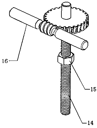
[0087] Embodiment 1: as Figure 1-7 As shown, a vibrating wire type infrasonic wave sensor based on PVDF includes a string horse I1, a vibrating string 2, a guide rail 3, a string horse II 4, a PVDF piezoelectric film 7, an elastic diaphragm 8, and a fixing bracket. The fixing bracket includes a clip String device Ⅰ5, steel plate Ⅰ6, right bottom plate 9, string clamping device Ⅱ11, steel plate Ⅱ12, ring part 13; wherein the string bridge Ⅰ1 is installed at the center of the elastic diaphragm 8, and the vibrating string 2 as a receiving element is controlled by the string clamping device Ⅰ5 The string clamping device II11 is fixed and supported by the bridge I1 and the bridge II4. The guide rail 3 is installed on the bottom plate 9 on the right side and has a scale. The electric film 7, the right bottom plate 9 is located on the right side of the fixed bracket, the ring part 13 is located on the left side of the fixed bracket, the steel plate I6 and the steel plate II12 are lo...
Embodiment 2
[0096] Embodiment 2: as Figure 1-7 As shown, a vibrating wire type infrasonic wave sensor based on PVDF includes a string horse I1, a vibrating string 2, a guide rail 3, a string horse II 4, a PVDF piezoelectric film 7, an elastic diaphragm 8, and a fixing bracket. The fixing bracket includes a clip String device Ⅰ5, steel plate Ⅰ6, right bottom plate 9, string clamping device Ⅱ11, steel plate Ⅱ12, ring part 13; wherein the string bridge Ⅰ1 is installed at the center of the elastic diaphragm 8, and the vibrating string 2 as a receiving element is controlled by the string clamping device Ⅰ5 The string clamping device II11 is fixed and supported by the bridge I1 and the bridge II4. The guide rail 3 is installed on the bottom plate 9 on the right side and has a scale. The electric film 7, the right bottom plate 9 is located on the right side of the fixed bracket, the ring part 13 is located on the left side of the fixed bracket, the steel plate I6 and the steel plate II12 are lo...
Embodiment 3
[0104] Embodiment 3: as Figure 1-7 As shown, a vibrating wire type infrasonic wave sensor based on PVDF includes a string horse I1, a vibrating string 2, a guide rail 3, a string horse II 4, a PVDF piezoelectric film 7, an elastic diaphragm 8, and a fixing bracket. The fixing bracket includes a clip String device Ⅰ5, steel plate Ⅰ6, right bottom plate 9, string clamping device Ⅱ11, steel plate Ⅱ12, ring part 13; wherein the string bridge Ⅰ1 is installed at the center of the elastic diaphragm 8, and the vibrating string 2 as a receiving element is controlled by the string clamping device Ⅰ5 The string clamping device II11 is fixed and supported by the bridge I1 and the bridge II4. The guide rail 3 is installed on the bottom plate 9 on the right side and has a scale. The electric film 7, the right bottom plate 9 is located on the right side of the fixed bracket, the ring part 13 is located on the left side of the fixed bracket, the steel plate I6 and the steel plate II12 are lo...
PUM
 Abstract
Description
Claims
Application Information
 - R&D
- Intellectual Property
- Life Sciences
- Materials
- Tech Scout
- Unparalleled Data Quality
- Higher Quality Content
- 60% Fewer Hallucinations
Browse by: Latest US Patents, China's latest patents, Technical Efficacy Thesaurus, Application Domain, Technology Topic, Popular Technical Reports.
© 2025 PatSnap. All rights reserved.Legal|Privacy policy|Modern Slavery Act Transparency Statement|Sitemap|About US| Contact US: help@patsnap.com


