Transport container for nuclear fuel assemblies and use of said container

Active Publication Date: 2012-09-04
AREVA NP SAS
View PDF11 Cites 2 Cited by
  • Summary
  • Abstract
  • Description
  • Claims
  • Application Information

AI Technical Summary

Benefits of technology

[0005]In this context, an object of the invention is to provide a container which is suitable

Problems solved by technology

Since each type of assembly has a specific cross-section and specific grid positions, it is n

Method used


Image

  • Transport container for nuclear fuel assemblies and use of said container
  • Transport container for nuclear fuel assemblies and use of said container
  • Transport container for nuclear fuel assemblies and use of said container

Examples


Example

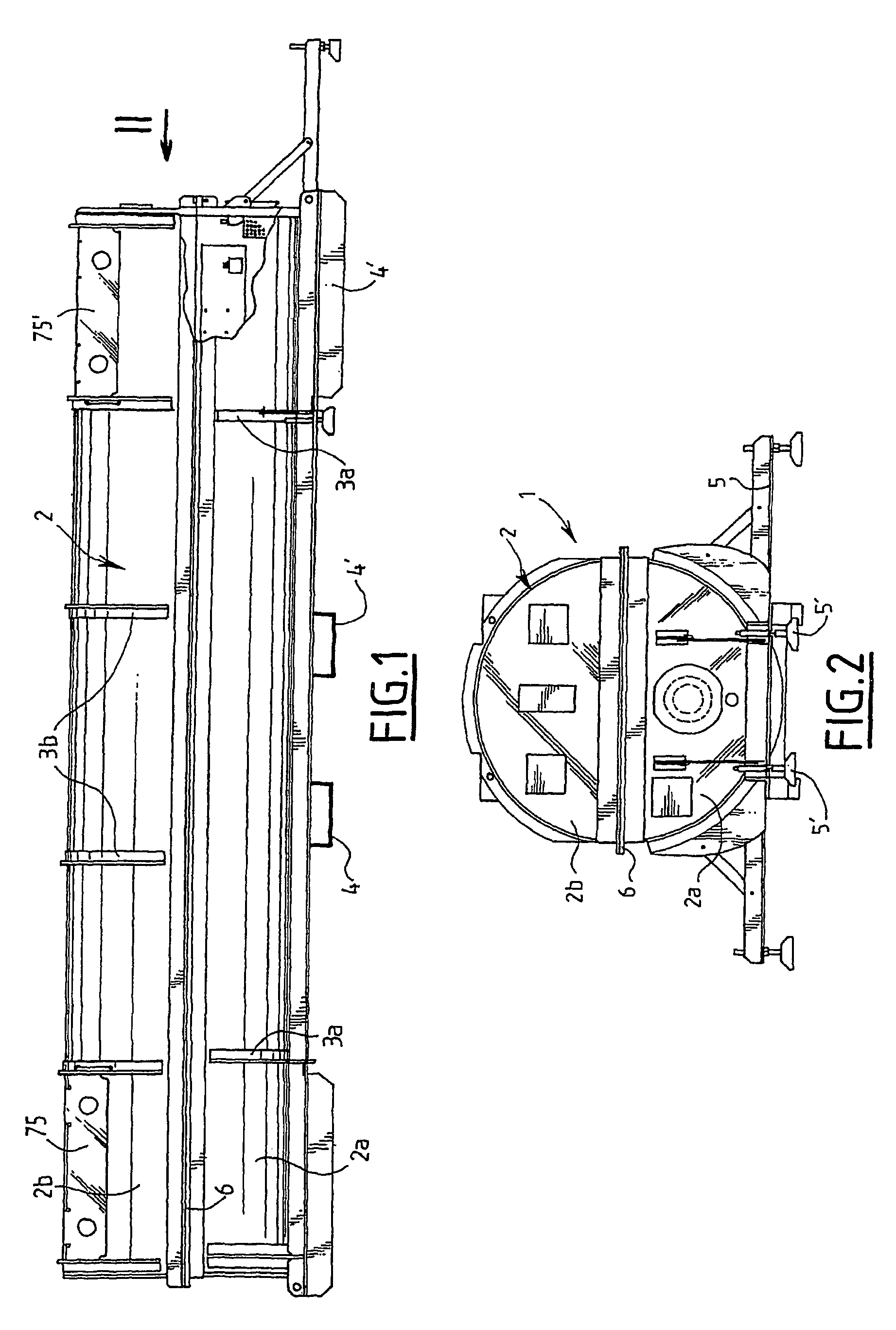
[0026]FIGS. 1 and 2 show a container 1 for transporting fresh fuel assemblies for a pressurized water nuclear reactor.

[0027]The transport container 1, which is intended to transport two fuel assemblies in the horizontal position, comprises an external casing 2 formed by a lower half-shell 2a and an upper half-shell 2b mounted one on top of the other in accordance with a junction plane.

[0028]Each of the half-shells 2a and 2b is produced from sheet-steel and comprises respective reinforcing bows 3a, 3b distributed along the length of the half-shell.

[0029]Sectional members 4 and 4′ forming support feet for the container are also secured to the lower portion of the lower half-shell 2a. In addition, adjustable bearing members 5 and 5′ which comprise screw jacks and which are fixedly joined to a longitudinal end portion of the container enable the inclination of the container resting on a support surface to be adjusted, about the longitudinal axis of the container and about a transverse a...


PUM


Abstract

A container including a support having at least one first longitudinal support surface defining a longitudinal housing for receiving a nuclear fuel assembly, and a door having a second longitudinal support surface. The door is movable between a position of holding the nuclear fuel assembly between the two longitudinal surfaces and a released position in which the assembly is free with respect to the support. The container includes means for adjusting the transversal separation between the first and second surfaces in the holding position of the door.

Description

[0001]Priority is claimed to French Application Serial No. FR 06 07424 filed Aug. 21, 2006 through International Patent Application Serial No. PCT / FR2007 / 001032, filed Jun. 21, 2007.[0002]The invention relates in general to transport containers for nuclear fuel assemblies.[0003]To be more precise, the invention relates, according to a first aspect, to a transport container for nuclear fuel assemblies of elongate shape in a longitudinal direction, of the type comprising a support having at least a first longitudinal bearing surface delimiting a longitudinal housing for receiving a nuclear fuel assembly, and a door having a second longitudinal bearing surface, the door being movable between a position holding the nuclear fuel assembly between the two longitudinal surfaces and a release position in which the assembly is free with respect to the support.BACKGROUND[0004]The document WO-99 / 41754 describes such a container. In this container, the second longitudinal surface rests on a nucl...

Claims


Application Information

Patent Timeline
IPC IPC(8): G21C19/00
CPCG21F5/008G21Y2004/30G21Y2002/304
Inventor GAUTHIER, JACQUESWEGELER, PIERREROILLET, SERGE
Owner AREVA NP SAS
Why Eureka
Try Eureka