Electrical connector

a technology of electric connectors and connectors, applied in the direction of contact members penetrating/cutting insulation/cable strands, electrical appliances, fastening/insulating connecting parts, etc., can solve the problems of wasting working time, complex and inability to connect the assistant terminal to the cable, and achieve simple connection operation and restore the resilience of the bend portion

Inactive Publication Date: 2012-09-11
CHENG UEI PRECISION IND CO LTD
View PDF9 Cites 87 Cited by
  • Summary
  • Abstract
  • Description
  • Claims
  • Application Information

AI Technical Summary

Benefits of technology

[0005]An object of the present invention is to provide an electrical connector for connecting with a cable. The electrical connector includes an insulating housing defining an accommodating space which is surrounded among a bottom wall, a front wall, a rear wall and two side walls. A front of the bottom wall protrudes upward into the accommodating space to form a protrusion, and a pivot pillar is further protruded upward from a top of the protrusion. A connecting terminal is positioned in the accommodating space and has a base plate against the bottom wall. Two opposite side edges of the base plate extend upward to form a connecting plate at a front thereof and a side plate which abut against the side walls respectively. A clipping piece is connected with a rear edge of the connecting plate and freely inclined towards the side plate. A clipping terminal is positioned in the accommodating space and has a resisting board vertically abutting against an inside of the side plate to realize an electrical connection with the connecting terminal. A bend portion is bent towards the resisting board from a front edge of the resisting board and put around the protrusion. A rear edge of the bend portion extends rearward and is inclined oppositely to the resisting board to form a clipping board of which a rear edge is substantially against an inside of the clipping piece.

Problems solved by technology

However, the foregoing connection operation between the assistant ter

Method used


Image

  • Electrical connector
  • Electrical connector
  • Electrical connector

Examples


Embodiment Construction

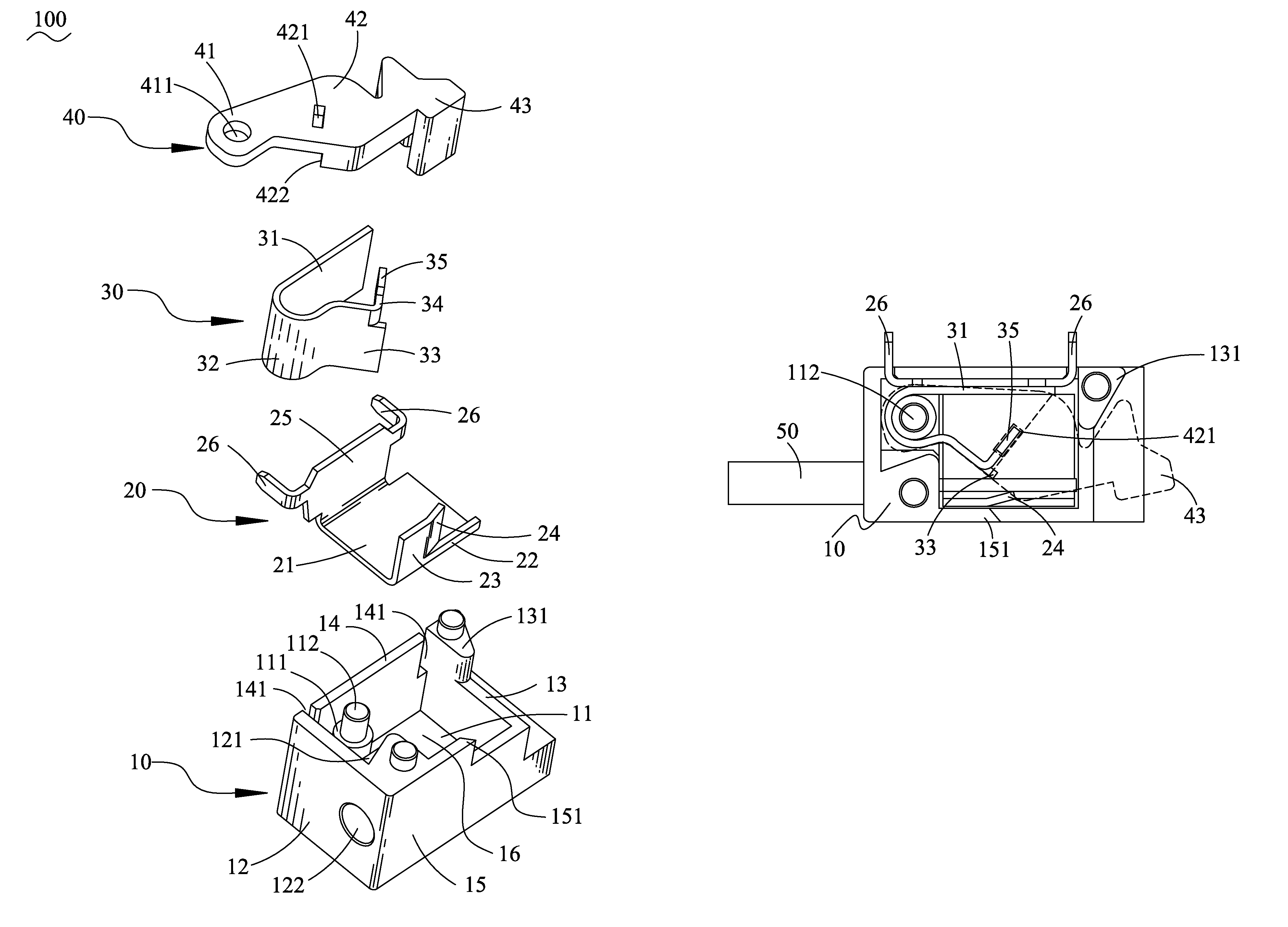
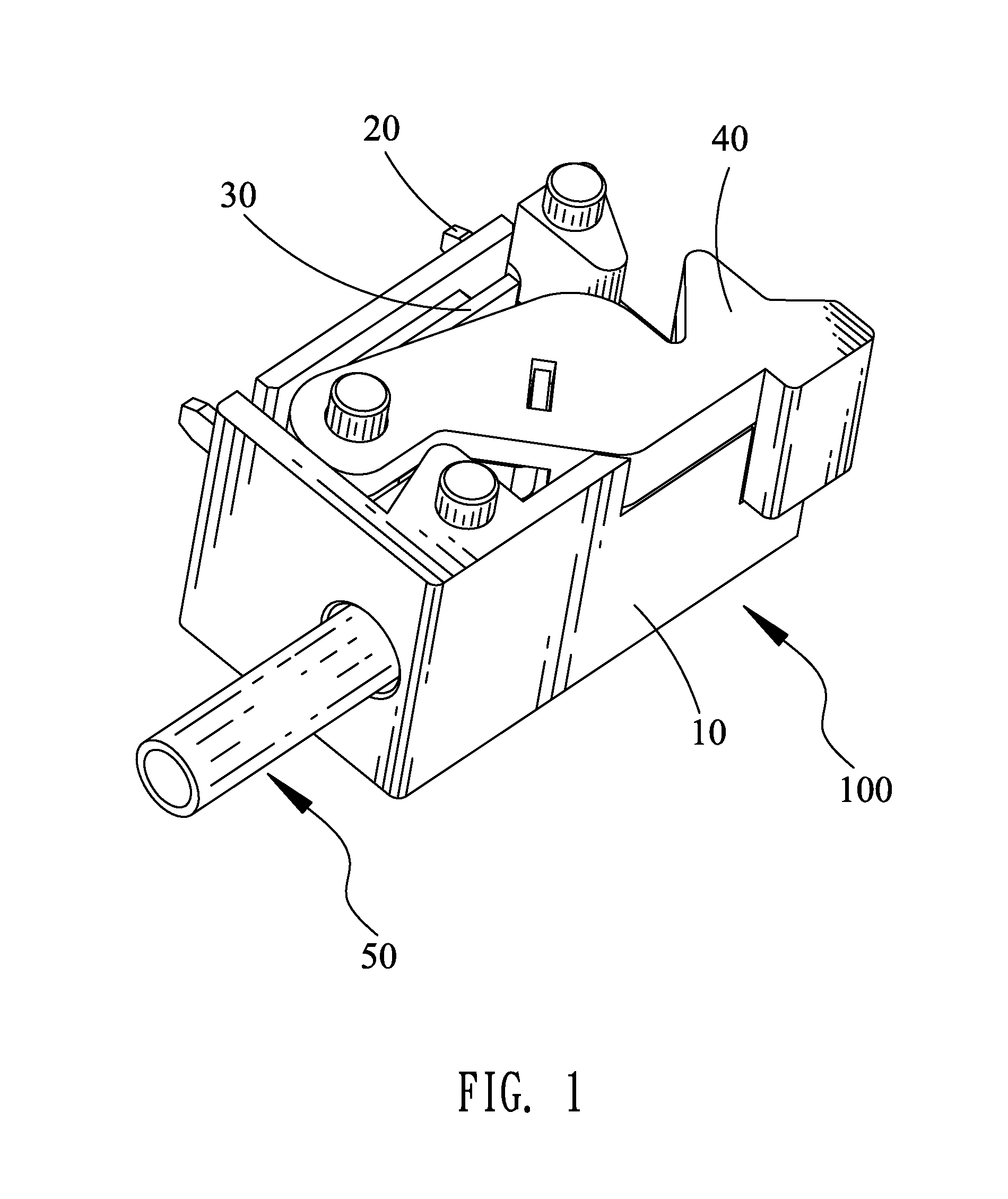
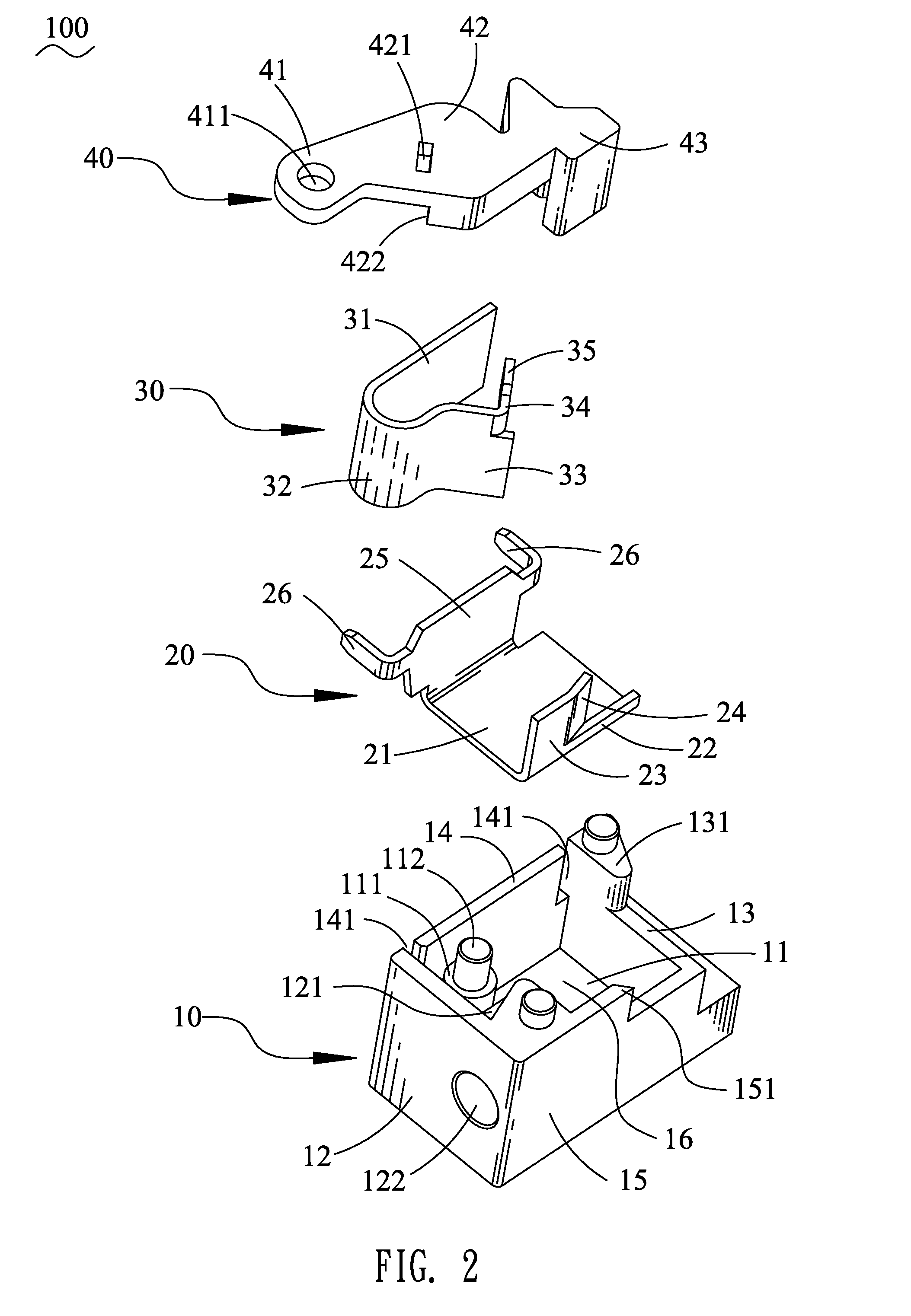
[0014]With reference to FIG. 1, an electrical connector 100 in accordance with an embodiment of the present invention is shown. The electrical connector 100 is adapted for connecting a cable 50 with a printed circuit board (not shown). The electrical connector 100 includes an insulating housing 10, a connecting terminal 20, a clipping terminal 30 and a whirling element 40.

[0015]Referring to FIG. 2, the insulating housing 10 has a bottom wall 11 of a rectangular shape, a front wall 12, a rear wall 13, a first side wall 14 and a second side wall 15 which are connected together to define an accommodating space 16 thereamong. An inside of the front wall 12 protrudes rearward to form a restraining block 121 adjacent to the second side wall 15. An inserting hole 122 penetrates through the restraining block 121 and the front wall 12 along a front-to-rear direction to be communicated with the accommodating space 16. A front of a top side of the bottom wall 11 protrudes upward to form a cyli...


PUM


Abstract

An electrical connector includes an insulating housing having a protrusion with a pivot pillar at a top thereof. A connecting terminal is positioned in the insulating housing and has a base plate, a connecting plate, a side plate and a clipping piece slantwise extending inward from a rear edge of the connecting plate. A clipping terminal has a resisting board against the side plate, a clipping board inclined towards the clipping piece and a bend portion connecting the resisting board and the clipping board to be put around the protrusion. A rear edge of the clipping board slantwise extends inward to form a resisting arm having a buckling block at a top thereof. A whirling element is pivoted to the pivot pillar and defining a buckling hole for buckling the buckling block. The rotation of the whirling element drives the clipping board to secure or set free a cable.

Description

BACKGROUND OF THE INVENTION[0001]1. Field of the Invention[0002]The present invention generally relates to an electrical connector, and more particularly to an electrical connector capable of connecting with a cable.[0003]2. The Related Art[0004]A conventional electrical connector adapted for connecting a cable with a printed circuit board includes an insulating housing, an assistant terminal and a conductive terminal which are assembled in the insulating housing and electrically connect with each other. The conductive terminal is adapted to be soldered with the printed circuit board. The assistant terminal has a connecting portion with a wedging hole being opened therein. When the cable need be connected to the electrical connector, a conductive core of one end of the cable is inserted into the wedging hole of the connecting portion of the assistant terminal. Then the conductive core is further soldered together with the connecting portion of the assistant terminal. So, an electric...

Claims


Application Information

Patent Timeline
IPC IPC(8): H01R4/48
CPCH01R4/4836H01R12/515H01R4/48365
Inventor CHIANG, CHIH-HSIEN
Owner CHENG UEI PRECISION IND CO LTD
Why Eureka
Try Eureka