Connecting structure for bus bar and electrical wire

a technology of connecting structure and bus bar, which is applied in the direction of connection contact member material, current conducting connection, cell components, etc., can solve the problems of poor connection reliability, complicated connection operation, heat generation, etc., and achieve the effect of preventing impairment of electrical connection performance, reducing the number of connections, and no increase in contact resistan

Active Publication Date: 2017-10-31
YAZAKI CORP
View PDF35 Cites 2 Cited by
  • Summary
  • Abstract
  • Description
  • Claims
  • Application Information

AI Technical Summary

Benefits of technology

[0013]An object of the present invention is to provide a connecting structure for a bus bar and an electrical wire, which achieves a simple connecting operation for the bus bar and the electrical wire and does not impair electrical connection performance even if the bus bar or a core wire of the electrical wire is made of an aluminum material.
[0017]According to the first aspect of the present invention, at least one of the bus bar-connecting section and the electrical wire-connecting section of the crimp terminal is provided with the oxide film breaking means for breaking the oxide film on the bus bar or the core wire on the end of the electrical wire. Therefore, even if the bus bar or the core wire on the end of the electrical wire is made of an aluminum material and an oxide film develops on the surface of the aluminum material, the oxide film can be broken by crimping the crimp terminal. As a result, there is no increase in contact resistance due to the oxide film, which in turn enables preventing impairment of electrical connection performance of the bus bar or the core wire on the end of the electrical wire.
[0018]A connection between the bus bar and the core wire on the end of the electrical wire and fixing of the coating portion of the electrical wire can be accomplished merely by a process for crimping the crimp terminal to the bus bar and the electrical wire. Therefore, the number of processes for connection is reduced, thus achieving a simplification of a connection operation.
[0019]According to the second aspect of the present invention, the crimp terminal includes the bus bar-connecting section, the core wire crimp portion, and the coating clamping portion. Thus, the connection between the bus bar and the core wire on the end of the electrical wire and the fixing of the coating portion of the electrical wire can be accomplished merely by crimping the crimp terminal to the bus bar and the electrical wire. Therefore, the simplification of the connection operation is achieved.
[0020]The oxide film breaking means is the serration formed on at least one of the bus bar-connecting section and the core wire crimp portion of the crimp terminal. Thus, edge portions of the serration bite into the bus bar or the core wire on the end of the electrical wire, thereby breaking the oxide film. Therefore, there is no increase in the contact resistance due to the oxide film, which in turn enables preventing the impairment of the electrical connection performance of the bus bar or the core wire on the end of the electrical wire.
[0021]According to the third aspect of the present invention, the serration or the plural ridges configured to restrain the axial misalignment of the core wire and thereby retain the core wire, are formed on the core wire crimp portion of the crimp terminal. Therefore, even if the core wire is made of the aluminum material, the oxide film on the core wire can be broken, and a good connection between the electrical wire and the crimp terminal can be achieved.

Problems solved by technology

Therefore, this structure has the problem of impairing reliability of connection.
In this case, however, a process for welding the core wire and a process for clamping the coating portion of the electrical wire are necessary, thus leading to a complicated connection operation.
The oxide film increases contact resistance on a crimp surface of the bus bar and the electrical wire, thus leading to the problem of causing heat generation or the like.

Method used


Image

  • Connecting structure for bus bar and electrical wire
  • Connecting structure for bus bar and electrical wire
  • Connecting structure for bus bar and electrical wire

Examples


Embodiment Construction

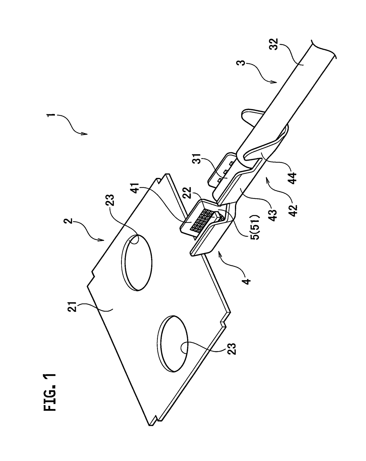
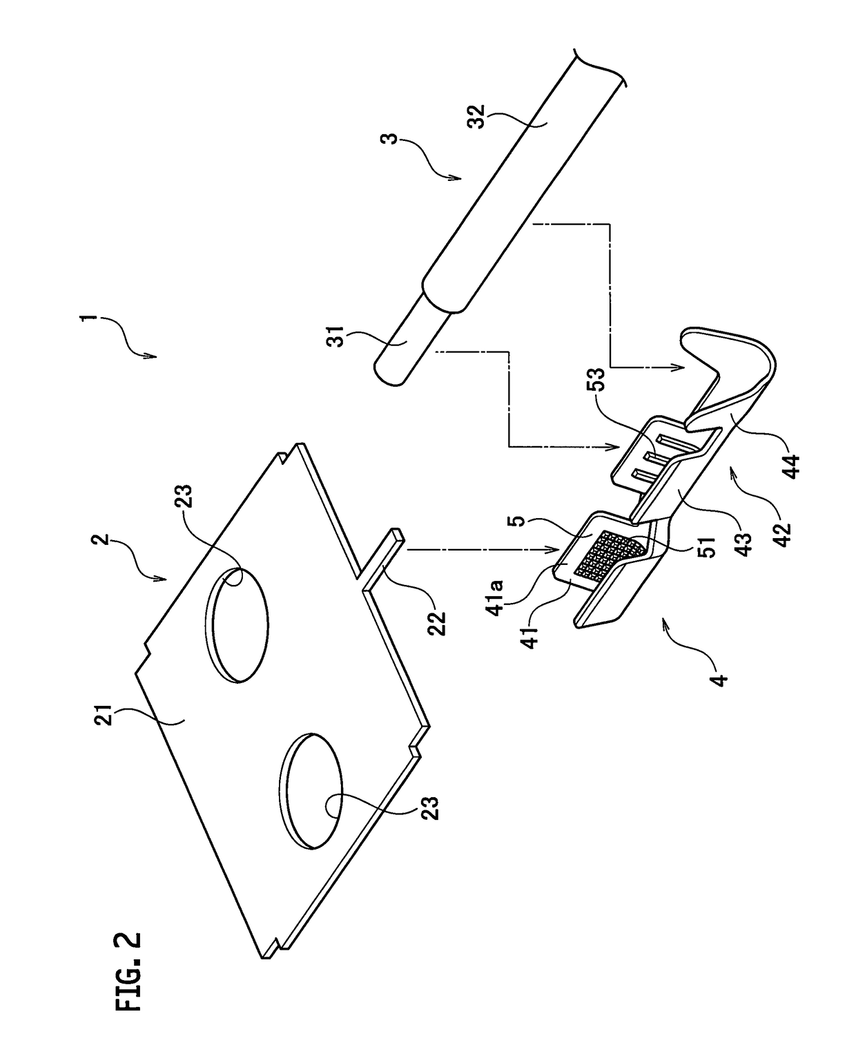
[0025]An embodiment of the present invention will be described in detail below with reference to FIGS. 1 to 3.

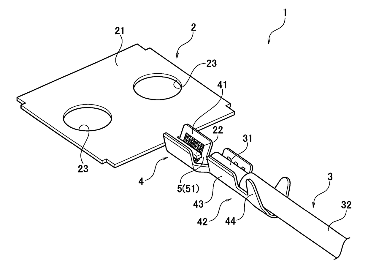
[0026]A connecting structure 1 uses a crimp terminal 4 to connect a bus bar 2 and an electrical wire 3 together. The connecting structure 1 is used in a power supply device mounted on an electric vehicle or a hybrid vehicle.

[0027]The power supply device (not illustrated) includes plural battery cells arranged side by side. Each of the battery cells has one end at which a positive electrode and a negative electrode protrude. The plural battery cells are arranged in such a manner that the positive electrode of one of the adjacent battery cells is connected to the negative electrode of the other battery cell. The bus bar 2 connects the adjacent battery cells in series or provides a connection between the battery cell and an external device. Thus, the number of the bus bars 2 for use in the connecting structure 1 is set according to the number of battery cells and the number of ...


PUM

PropertyMeasurementUnit
widthaaaaaaaaaa
shapeaaaaaaaaaa
voltageaaaaaaaaaa

Abstract

A connecting structure uses a crimp terminal to connect a bus bar and an electrical wire together. The crimp terminal includes a bus bar-connecting section to be crimped to the bus bar, and an electrical wire-connecting section to be crimped to an end of the electrical wire. At least one of the bus bar-connecting section and the electrical wire-connecting section is provided with an oxide film breaking means for breaking an oxide film on the bus bar or a core wire on the end of the electrical wire.

Description

CROSS REFERENCE TO RELATED APPLICATION[0001]This is a continuation application based on PCT application No. PCT / JP2013 / 075125 filed on Sep. 18, 2013, which claims the benefit of priority from Japanese Patent Application No. 2012-205335 filed on Sep. 19, 2012, the entire contents of which are incorporated by reference herein.BACKGROUND OF THE INVENTION[0002]1. Field of the Invention[0003]The present invention relates to a connecting structure for a bus bar and an electrical wire, and more particularly to a connecting structure for a bus bar and an electrical wire, for use in a power supply device mounted on an electric vehicle or a hybrid vehicle.[0004]2. Description of the Related Art[0005]An electric vehicle using an electric motor to travel or a hybrid vehicle using an electric motor in combination with an engine to travel needs a power supply device which supplies a high voltage and a high output to the electric motor, in order to travel smoothly. As the power supply device, a po...

Claims


Application Information

Patent Timeline
Patent Type & Authority Patents(United States)
IPC IPC(8): H01R11/11H01M2/20H01R4/18H01R11/05H01M2/32H01R4/62H01M50/50H01M50/503H01M50/571
CPCH01R11/11H01M2/20H01M2/206H01M2/32H01R4/184H01R4/185H01R4/188H01R11/05H01R4/182H01R4/62Y02E60/10H01M50/50H01M50/571H01M50/503
Inventor YOSHIOKA, NOBUAKISUZUKI, KEIGO
Owner YAZAKI CORP
Why Eureka
Try Eureka