Electricity storage module
a technology of storage module and electric power, applied in the direction of battery, sustainable manufacturing/processing, cell components, etc., can solve the problems of cumbersome connection operation and reduce mounting space, so as to reduce space, enhance electrical connection reliability, and suppress the occurrence of electrolytic corrosion
- Summary
- Abstract
- Description
- Claims
- Application Information
AI Technical Summary
Benefits of technology
Problems solved by technology
Method used
Image

Examples
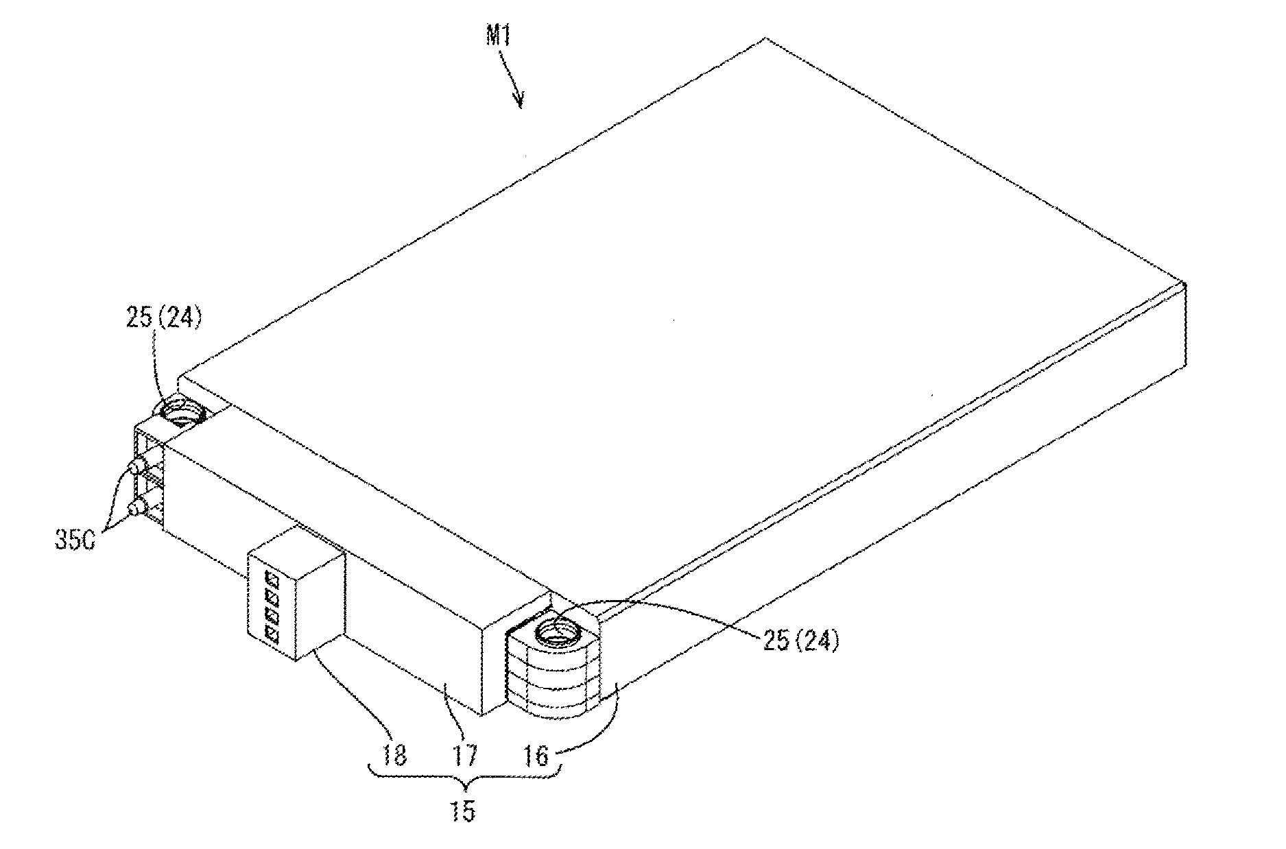
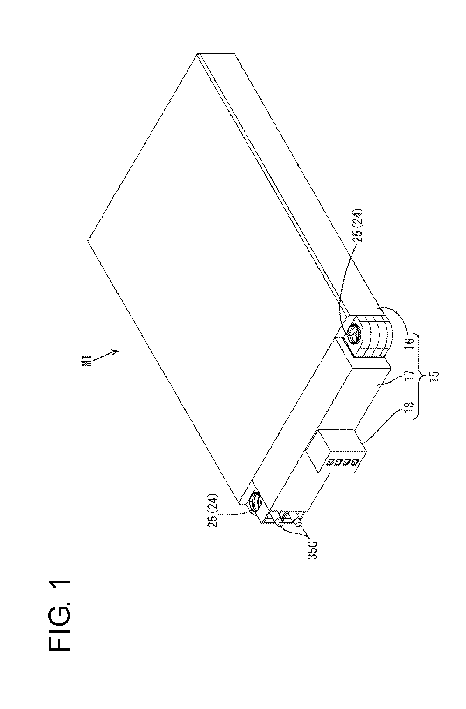
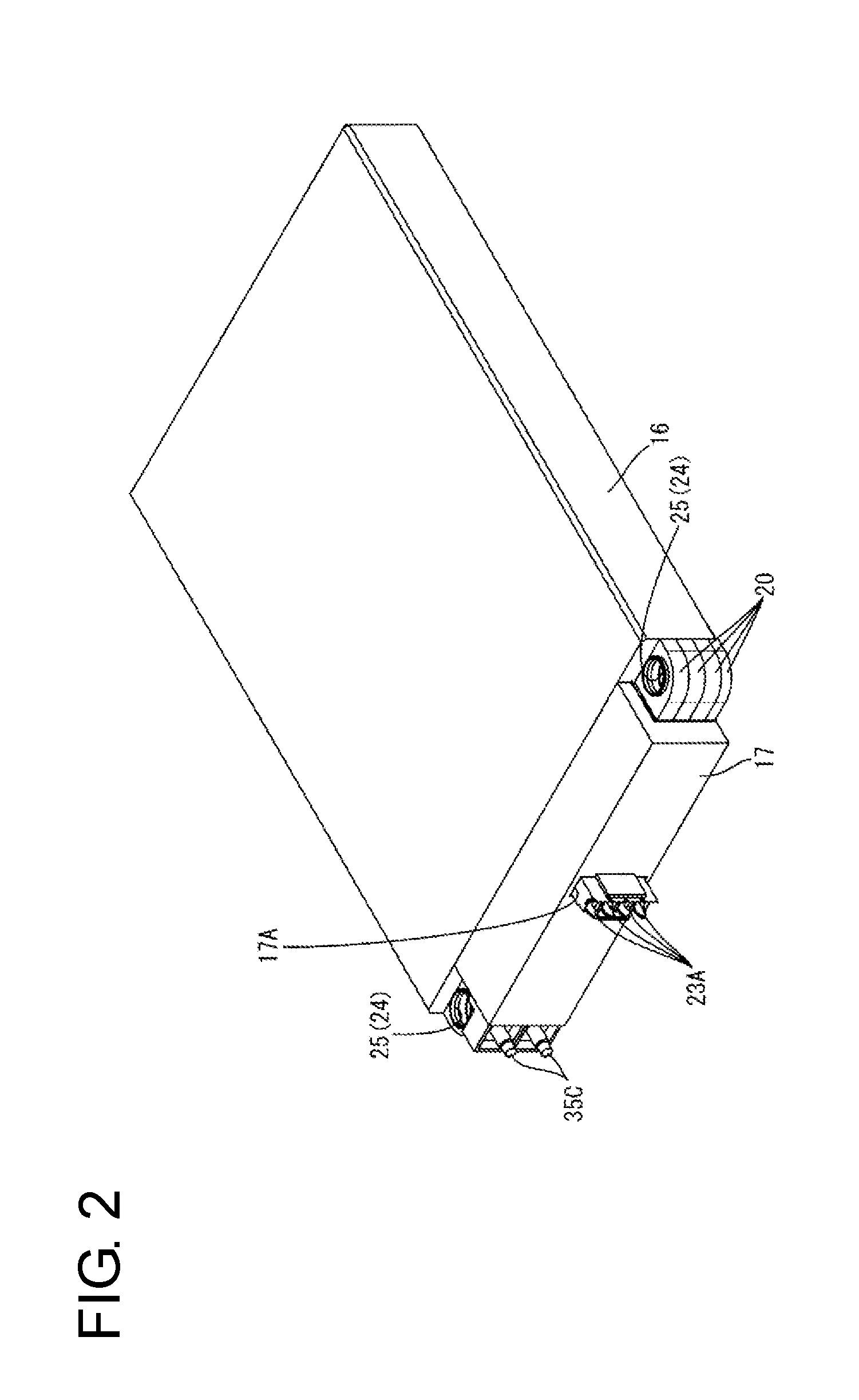
case 15
[0053](Case 15)
[0054]The case 15 includes a case main body 16 configured to accommodate the electricity storage element group 10 and having an open front side, a holding member cover 17 for covering the holding members 20 arranged at an outer side of an opening of the case main body 16 and a housing 18 mounted on the holding member cover 17. In this embodiment, all the electricity storage elements 11 are accommodated in one case main body 16.
[0055]The holding member cover 17 covers parts except external connection terminals 35C and fixing portions 24 and terminal accommodating portions 23 formed on the holding members 20.
[0056]As shown in FIG. 2, an insertion portion 17A through which the terminal accommodating portions 23 provided on the holding members 20 are insertable is provided in a center of the holding member cover 17. As shown in FIG. 1, the housing 18 for covering the terminal accommodating portions 23 is mounted on the insertion portion 17A provided on the holding member ...
PUM
| Property | Measurement | Unit |
|---|---|---|
| distance | aaaaa | aaaaa |
| shape | aaaaa | aaaaa |
| thickness | aaaaa | aaaaa |
Abstract
Description
Claims
Application Information
 - R&D
- Intellectual Property
- Life Sciences
- Materials
- Tech Scout
- Unparalleled Data Quality
- Higher Quality Content
- 60% Fewer Hallucinations
Browse by: Latest US Patents, China's latest patents, Technical Efficacy Thesaurus, Application Domain, Technology Topic, Popular Technical Reports.
© 2025 PatSnap. All rights reserved.Legal|Privacy policy|Modern Slavery Act Transparency Statement|Sitemap|About US| Contact US: help@patsnap.com