Golf hole painter

Active Publication Date: 2012-09-25
STANDARD GOLF
View PDF15 Cites 4 Cited by
  • Summary
  • Abstract
  • Description
  • Claims
  • Application Information

AI Technical Summary

Benefits of technology

[0009]It is therefore a principal object, feature, or advantage of the present invention to provide an improved apparatus and method for painting the interior of a golf hole.
[0010]Another object, feature, or advantage of the present invention is to provide an improved method and apparatus for painting the interior of a golf hole that paints only a regulation sized strip between a golf cup and a putting surface.
[0011]Another object, feature, or advantage of the present invention is to provide an improved method and apparatus for painting the interior of a golf hole to aid in a golfer's view of a golf hole.
[0012]Another object, feature, or advantage of the present invention is to provide an improved method and apparatus for painting the interior of a golf hole that does not rest on the putting surface.
[0013]Another object, feature, or advantage of the present invention is to provide an improved method and apparatus for painting the interior of a golf hole that paints the full interior periphery of the golf hole with one continuous stream of paint.
[0014]Another object, feature, or advantage of the present invention is to provide an improved method and apparatus for painting the interior of a golf hole that blocks a stream of paint from unintentionally spraying a golf cup in the hole.

Problems solved by technology

While a golfer may attempt to hit his or her ball as close to the hole as possible, there is a good chance that the ball may end up on a part of the green far from the hole.
Because the hole liners (i.e. cups) are sunk at least one inch below the putting green surface, the golfer may not be able to see the sunken cup from a distance.
Because dirt is earthen colored and does not provide much contrast with the putting surface, the golfer may have trouble detecting the location of the golf hole, which could result in missed putts.
However, this approach is time-consuming, and paint can easily spill on the cup or the putting surface of the green.
Again, this approach is time intensive, and it is difficult to apply the paint only where desired.
However, the apparatus described in the '305 patent suffers from several deficiencies.
First, the apparatus rests on the putting surface and thus has the potential for damaging or altering the otherwise smooth surface around the hole.
Another disadvantage is that the apparatus disclosed does not allow for the full interior periphery of a golf hole to be painted with one continuous motion.
Rather, when the spray canister is depressed and rotated, the arms extending into the hole block the stream of paint from the canister, which results in areas of the hole that are not painted.
Further, because the apparatus only has arms and a nozzle depresser disposed inside the hole, there is nothing to block the stream of paint from contacting the golf cup.

Method used


Image

  • Golf hole painter
  • Golf hole painter
  • Golf hole painter

Examples


Embodiment Construction

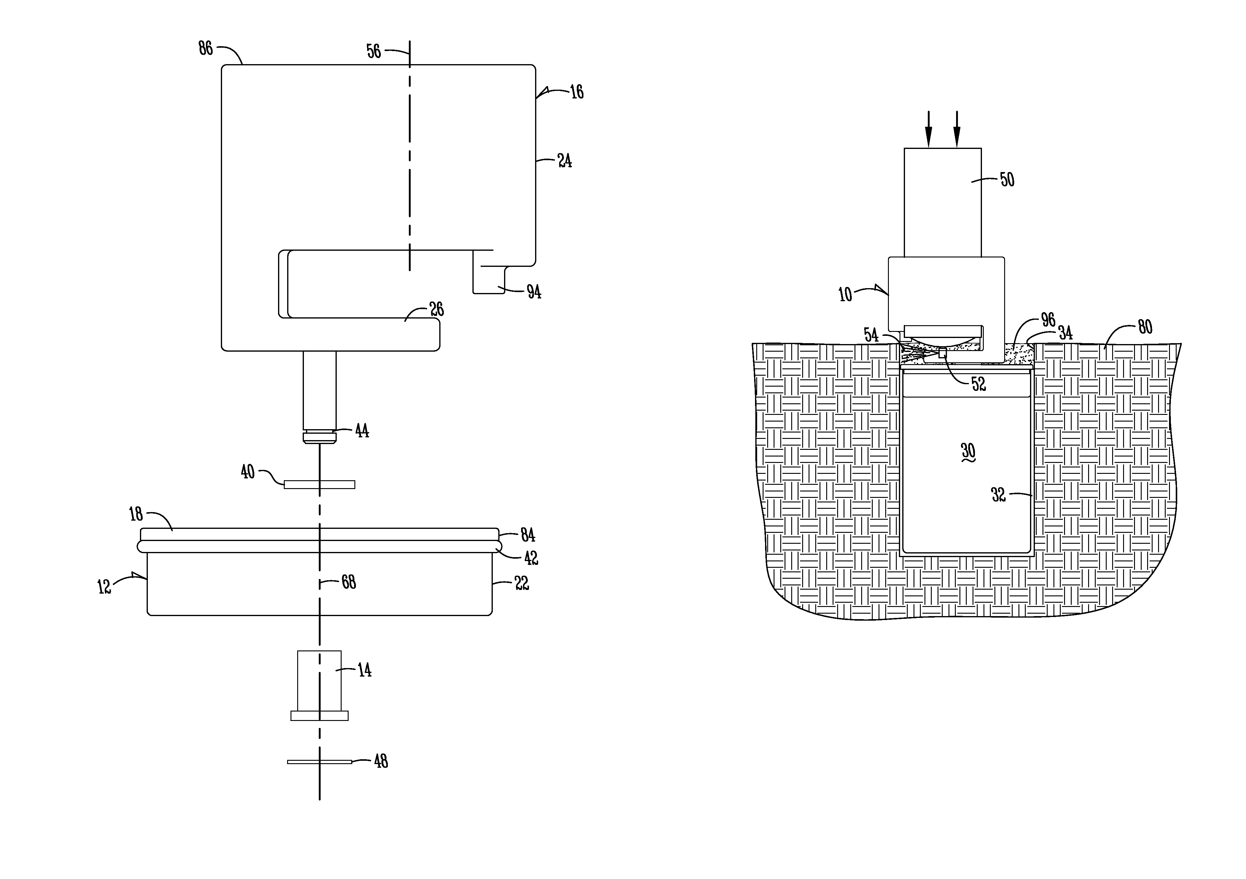
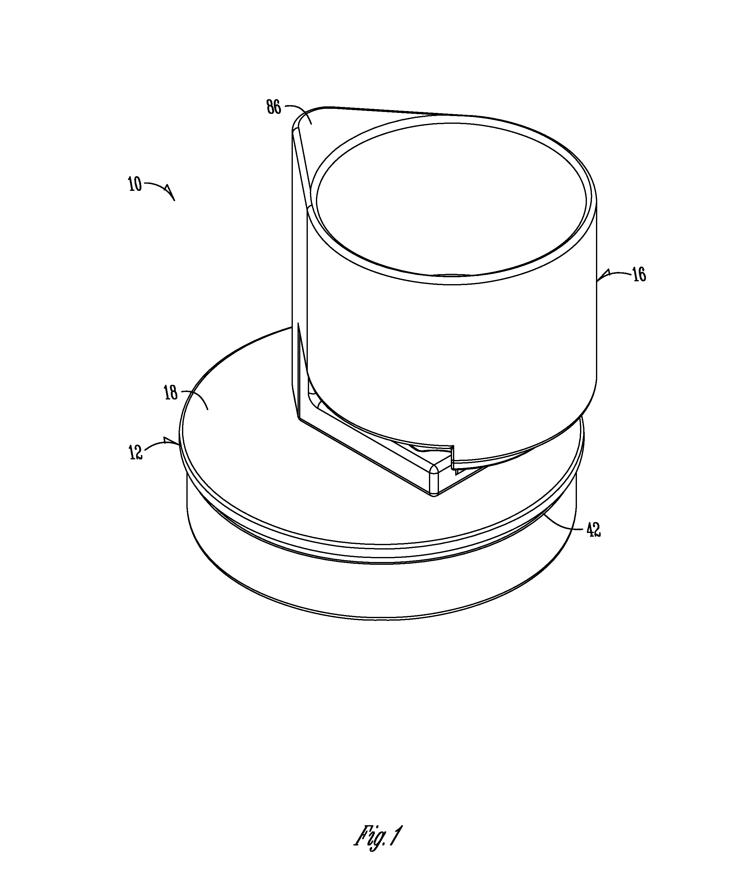
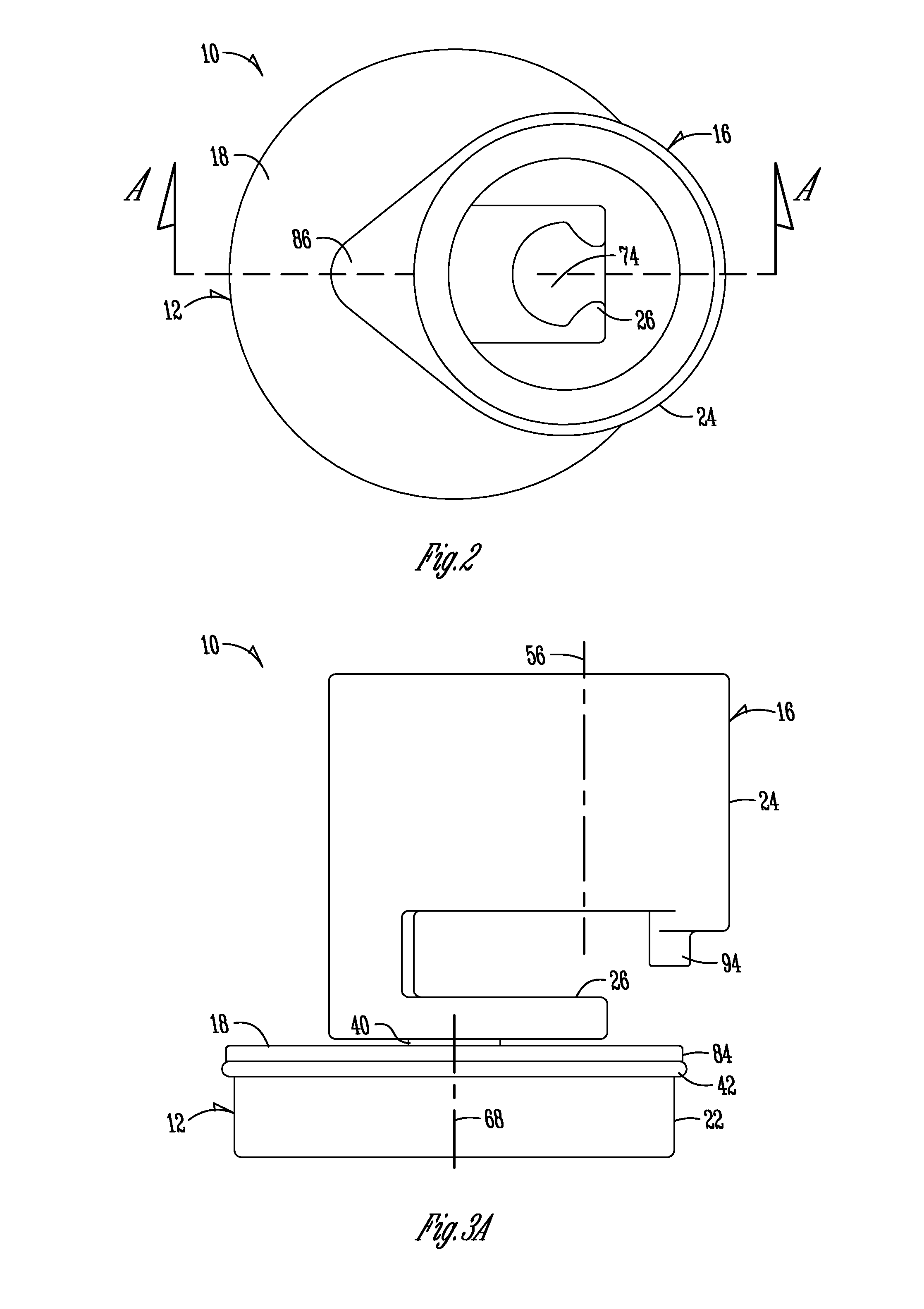
[0037]Referring to FIGS. 1-4, a golf hole painter is generally designated by the numeral 10. The golf hole painter 10 includes a base member 12, a liner 14, and a main body 16. As later discussed herein, the golf hole painter 10 may also include a washer 40 and an O-ring 42. Additionally, a snap ring 48 may be used.

[0038]Now referring to FIGS. 5-7, the base member 12 will be described in more detail. The base member 12 includes a top member 18, an aperture 20 through the top member 18, a wall 22 extending downwardly from the top member, and a base wall annular groove 46 around the wall 22. While the base wall annular groove 46 may be desired, it is not necessary in a preferred embodiment. A liner 14 may be press fit into the aperture 20 through the top member 18 of the base member 12. The base member may also include support members 60, which extend from the interior of the wall 22 towards the base member axis 68, but ending at the outer wall of the liner 14. As can be seen in FIG. ...


PUM

PropertyMeasurementUnit
Lengthaaaaaaaaaa
Angleaaaaaaaaaa
Diameteraaaaaaaaaa

Abstract

A golf hole painter is provided for painting an area of a golf hole above a top of a golf cup, but below the putting surface. The golf hole painter includes a base member, a liner, and a main body. The main body is rotatably attached to the base member. The main body also receives a spray canister containing paint, which is pressed and rotated along with the main body in relation to the base member to spray the entire interior periphery of a golf hole. The painted portion of the golf hole allows a golfer to more easily view a golf hole while putting on a golf green, due to the rules of golf requiring a golf cup to sit at least one inch below the putting surface.

Description

FIELD OF THE INVENTION[0001]The present invention relates generally to a golf hole painter, and more particularly to an improved method and apparatus for painting the interior wall of a golf hole at an area above the top of a golf cup.BACKGROUND OF THE INVENTION[0002]According to the United States Golf Association's (USGA) rules of golf, a golf hole must be 4.25 inches (108 mm) in diameter and at least 4 inches (101.6 mm) deep. If a lining is used, it must be sunk at least one inch (25.4 mm) below the putting green surface, unless the nature of the soil makes it impracticable to do so; however, its outer diameter must not exceed 4.25 inches (108 mm).[0003]While a golfer may attempt to hit his or her ball as close to the hole as possible, there is a good chance that the ball may end up on a part of the green far from the hole. Because the hole liners (i.e. cups) are sunk at least one inch below the putting green surface, the golfer may not be able to see the sunken cup from a distanc...

Claims


Application Information

Patent Timeline
IPC IPC(8): B05C7/02B05D1/02
CPCB05B3/02B05B13/0618B05B13/0636B05B13/069B05B15/061B65D83/386A63B57/0056B05D1/02B05D7/22A63B57/40A63B57/357B05B15/62
Inventor SCHOPPE, TERRY L.
Owner STANDARD GOLF
Why Eureka
Try Eureka