System and method for diverting flow to facilitate measurement of system parameters

a dynamic fluid system and flow system technology, applied in diagnostics, medical science, other medical devices, etc., can solve the problems of reversing affecting the flow of blood in the extracorporeal circuit, and affecting the flow of blood, so as to facilitate the determination of hemodynamic parameters

Active Publication Date: 2012-09-25
TRANSONIC SYST
View PDF6 Cites 2 Cited by
  • Summary
  • Abstract
  • Description
  • Claims
  • Application Information

AI Technical Summary

Benefits of technology

[0010]Thus, it is an objective of the present invention to provide a system and method for injecting a bolus of indicator that prevents the spike in pressure caused by the injection from disrupting the flow of blood in the extracorporeal circuit. It is a further objective to provide a system and method that maintains continuous blood flow in an extracorporeal circuit and avoids stoppage or reversal of blood flow during injection of a bolus in the extracorporeal circuit. It is an additional objective of the present invention to provide a system and method that prevents a pump regulating flow in the extracorporeal circuit from being slowed or stopped during injection of a bolus of indicator.
[0017]In another variation of the present invention it provides a system for facilitating the determination of hemodynamic parameters, which system has: a) an extracorporeal fluid conducting circuit with a first end that connects to an arterial catheter of a patient and a second end connecting to a venous catheter of a patient; b) a fluid propelling apparatus to move fluid through the extracorporeal circuit from the first end to the second end; c) at least one injection port on the extracorporeal circuit for access to the at least one conduit of the extracorporeal circuit; and d) an expandable reservoir in fluid communication with the extracorporeal fluid circuit at a position upstream on the extracorporeal circuit from the injection site for receiving accumulating fluid resulting from a constriction or interruption of flow downstream by an injection of an indicator and then releasing the accumulated fluid to flow down the extracorporeal circuit when the constriction or interruption of flow caused by the injection ceases.

Problems solved by technology

However, the sudden injection of the bolus of indicator creates problems and in fact can cause havoc to the flow of blood in the extracorporeal circuit.
The sudden injection into an extracorporeal blood circuit of a bolus of indicator, such as a saline solution, tends to disrupt the ordinary flow of blood in the extracorporeal blood circuit in that portion of the circuit upstream from the site of injection.
This sudden spike in pressure and interruption in flow of blood in the extracorporeal circuit typically results in a stoppage the flow of blood in the extracorporeal circuit upstream from the site of injection and quite often can cause a reversal of the flow of blood.
This sudden stoppage or reversal of flow, even though it is only for the period of injection, creates problems with the final readings obtained by the indicator dilution technique.
These problems can arise in passive systems where there is no pump or other device to regulate flow.
These problems are also significant problems in systems where the blood flow in the extracorporeal circuit has been induced by and is being regulated by a pump.
The slowing or stopping of the pump introduces inaccuracies into the readings ultimately obtained with the indicator dilution injection.

Method used


Image

  • System and method for diverting flow to facilitate measurement of system parameters
  • System and method for diverting flow to facilitate measurement of system parameters
  • System and method for diverting flow to facilitate measurement of system parameters

Examples


Embodiment Construction

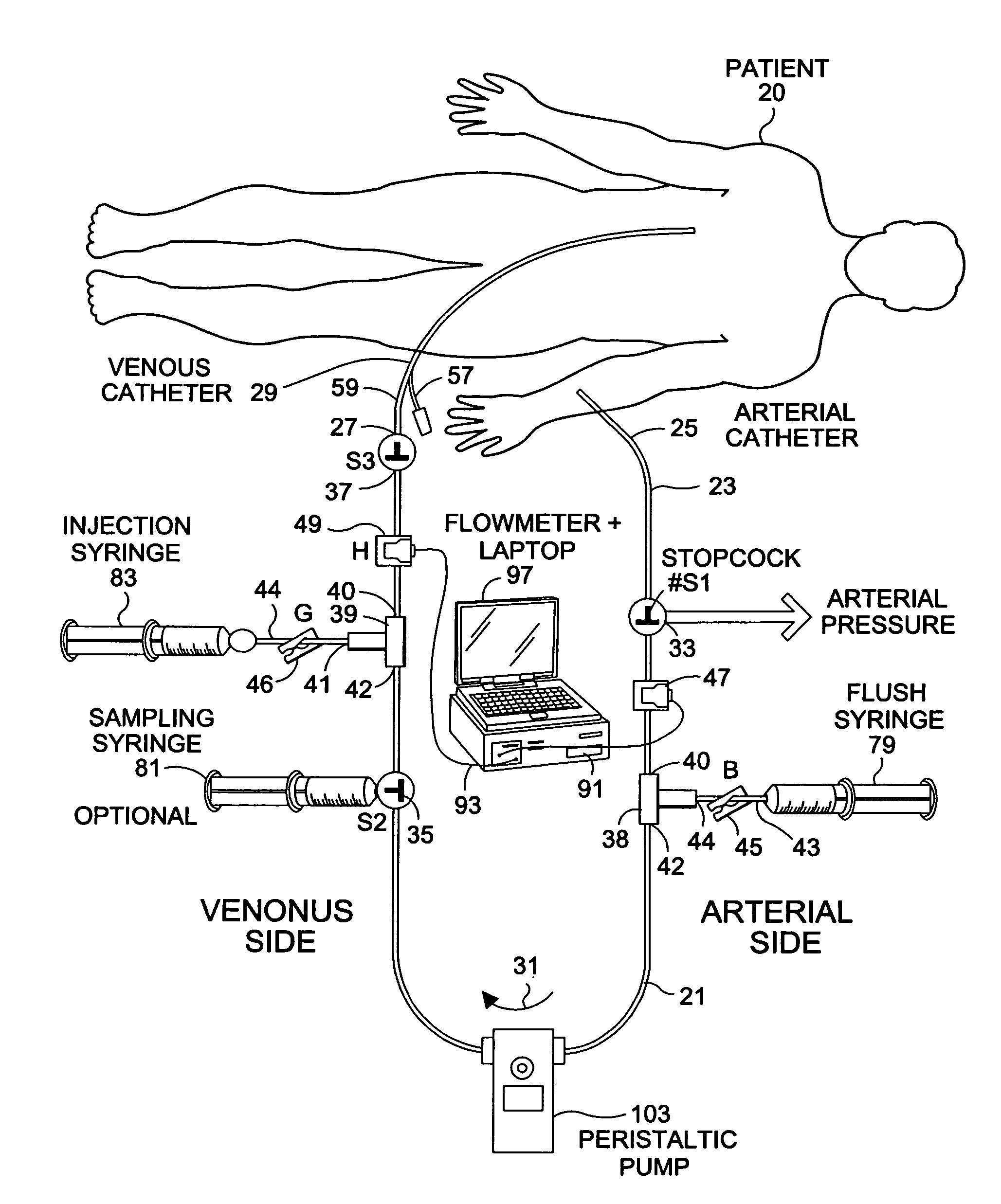
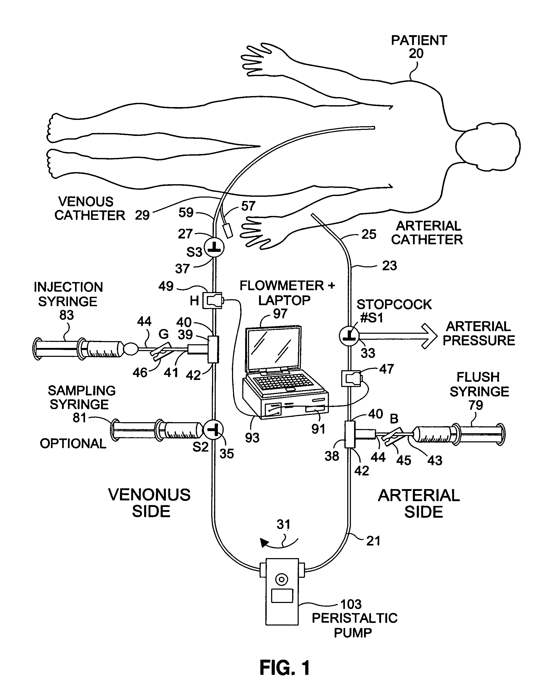
[0031]As noted above the present invention provides a method and system designed to facilitate the use of and indicator dilution technique for the determination of hemodynamic parameters in a circulatory system. Specifically it the invention facilities the injection of indicator. One example of a system and method where the present invention can be used is disclosed in pending U.S. patent application Ser. No. 11 / 370,721 filed Mar. 7, 2006 and titled System and Method for Determining Cardiac Blood Flow, which application is incorporated herein by reference as if set forth herein at length.

[0032]It should be noted that in this specification diverting will be utilized in its ordinary sense and to cover several possibilities to be discussed at length below, such as: 1) redirecting the flow to another location in the extracorporeal circuit or catheter to which the extracorporeal circuit attaches, or 2) accumulating the blood at a particular spot or location upstream from the site of inje...


PUM


Abstract

A method and various devices are disclosed that facilitates the measurement of hemodynamic parameters by injection of an indicator in an indicator dilution technique using an extracorporeal circuit connected to a patient. Specifically, the invention deals with problems caused by the spike in pressure in an extracorporeal line that result from the injection of a bolus. The method and various devices provide for diversion of blood during an indictor injection process and then return of the diverted blood back into the system after the injection is completed. The variations of the invention use diversion lines, accommodating cases and other devices that are designed to accumulate blood displaced during injection and then returning the blood to the extracorporeal circuit after injection.

Description

CROSS-REFERENCE TO RELATED APPLICATIONS[0001]The present application claims priority under 35 USC §119(e) from U.S. provisional application Ser. No. 60 / 922,863 filed on Apr. 11, 2007 titled System and Method for Redirecting Flow to Facilitate Measurement of System Parameters and U.S. provisional application Ser. No. 60 / 962,554 filed Jul. 30, 2007 and titled System and Method for Redirecting Flow to Facilitate Measurement of System Parameters.STATEMENT REGARDING FEDERALLY SPONSORED RESEARCH OR DEVELOPMENT[0002]Not applicable.REFERENCE TO A “SEQUENCE LISTING”[0003]Not applicable.FIELD OF THE INVENTION[0004]The present invention relates to a system and method for facilitating the determination of the physical parameters of a dynamic fluid system. More particularly it relates to a method for diverting flow during an indicator dilution procedure in an extracorporeal circulatory system to facilitate determination of various hemodynamic parameters.BACKGROUND OF THE INVENTION[0005]Indicator...

Claims


Application Information

Patent Timeline
Patent Type & Authority Patents(United States)
IPC IPC(8): A61M37/00
CPCA61B5/02028A61B5/0215A61B5/02152A61B5/0275A61M1/3621A61M1/367A61M1/3609
Inventor THURAMALLA, NAVEENKRIVITSKI, NIKOLAIALSBERGE, MARK
Owner TRANSONIC SYST
Why Eureka
Try Eureka