
Ink jet recording apparatus

a recording apparatus and jet technology, applied in printing and other directions, can solve the problems of unpredictability, unfavorable waste ink absorbing unit, and substantial amount of development effort, and achieve the effect of reducing water content, reducing the amount of bleeding, and reducing the amount of waste ink absorbency

Active Publication Date: 2012-10-09
CANON KK
View PDF34 Cites 2 Cited by
  • Summary
  • Abstract
  • Description
  • Claims
  • Application Information

AI Technical Summary

Benefits of technology

[0008]The first object of the present invention is to provide an innovative waste ink absorbing unit capable of enabling its ink absorbing member (made up of single or multiple ink absorbing portions) to fully display its natural function as an absorbent member, regardless of waste ink type, by analyzing how waste ink behaves as it is delivered to the ink absorbing portion of a waste ink absorbing unit.
[0009]The second object of the present invention is to provide a printer equipped with an innovative waste unit, which is not only significantly smaller in the amount of space it requires, but also, capable of continuously absorbing waste ink for a significantly longer period of time, and therefore, makes the printer more reliable than a printer equipped with a conventional ink absorbing unit.
[0010]The third object of the present invention is to provide an innovative waste ink absorbing unit, which is not affected in performance by the properties of its waste ink absorbing portion(s), remains effective even when waste ink is small in water content, and remains at a satisfactory level in performance for a preset length of time.
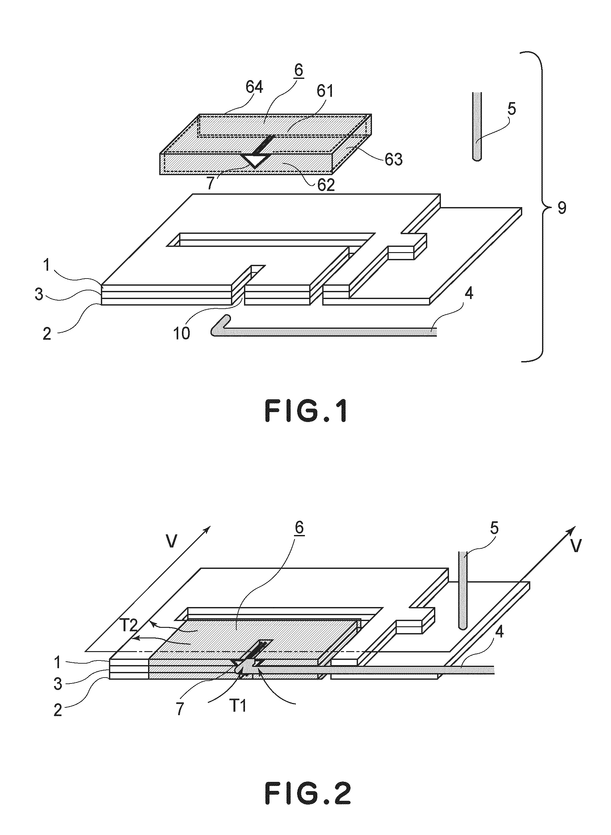
[0014]According to the present invention, a waste ink absorbing unit is made up of a waste ink absorbing member housing, a waste ink absorbing member made up of multiple waste ink absorbing portions, and a cover which functions as an evaporation retarding member. Therefore, even if it is used with a set of inks which has been improved to minimize “bleeding,” and also, from the standpoint of image preservation, the evaporation of the resultant waste ink is retarded by the cover. Therefore, the non-evaporative components in the waste ink are prevented from agglutinating on the surface of the waste ink absorbing portion, and / or inside the waste absorbing portion.
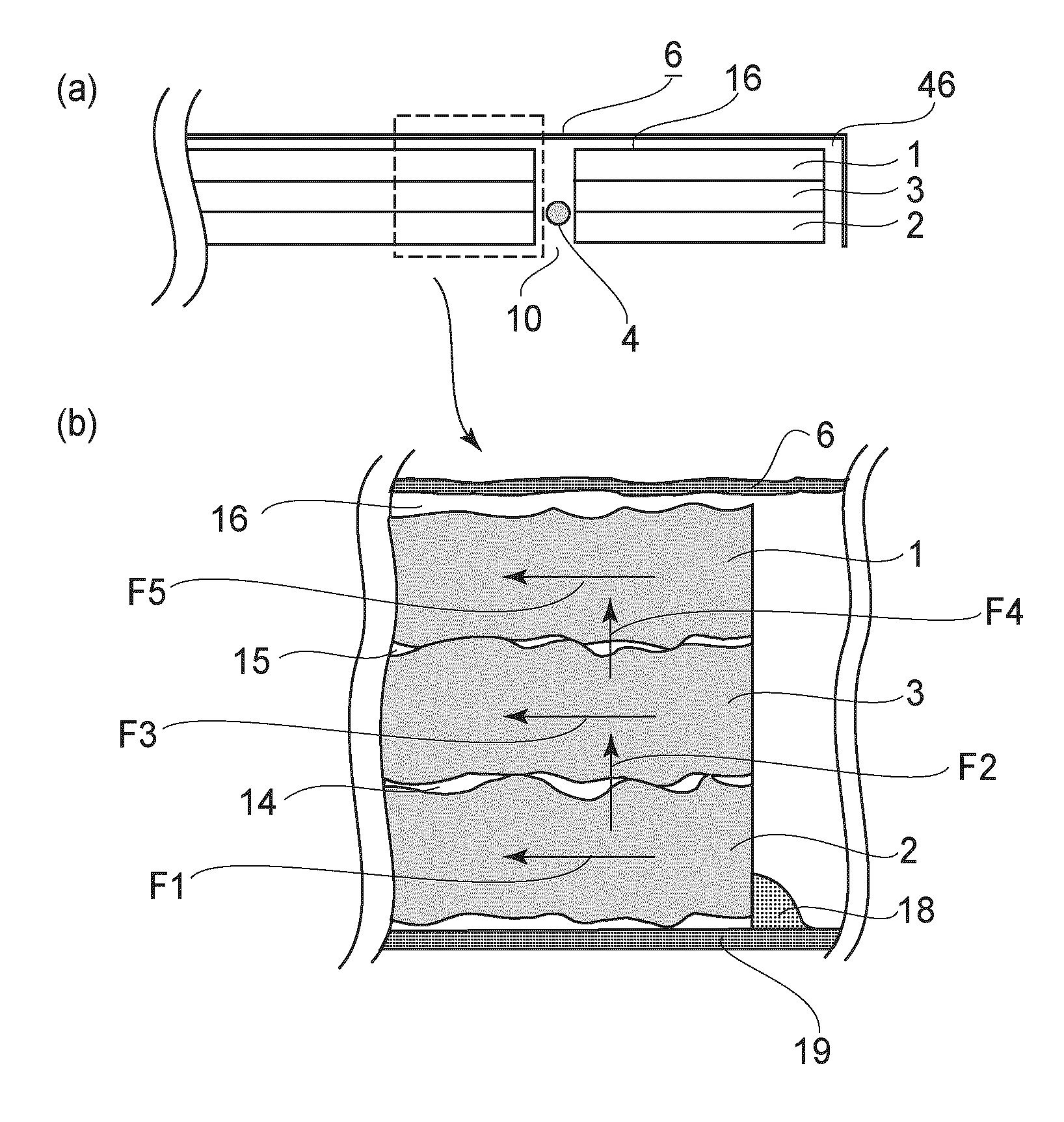
[0015]Also according to the present invention, the waste ink absorbing portions of a waste ink absorbing unit are simply stacked in layers so that minute spaces remain between the adjacent two waste ink absorbing portions. Therefore, proper balance is maintained between the amount by which the evaporative components in waste ink evaporate, and the amount by which waste ink diffuses in the waste ink absorbing portion(s), making it possible for waste ink to be absorbed throughout the waste ink absorbing portion(s), while preventing the waste ink absorbing portion(s) from reducing in waste ink absorbency. In other words, the present invention made it possible for a waste ink absorbing portion to fully display its natural function, making it possible for a waste ink absorbing unit to full displays its function, regardless of waste ink type.
[0016]Also according to the present invention, a waste ink absorbing portion is not impregnated with agglutination retarding liquid (which is generic term for glycerin or the like organic solvents). Therefore, it does not occur that waste ink quickly reduces in water content. Therefore, the present invention can solve the newly discovered problem that the quick reduction in the water content of waste ink, which is caused by the presence of agglutination retarding liquid in a waste ink absorbing portion, causes the non-evaporative components in waste ink to accumulatively deposit. Thus, the present invention is applicable to various ink jet recording apparatuses different in usage and the environment in which they are used. Further, it can prevent the problem that the interior of a recording apparatus, or a copy is soiled on its reverse side. In conclusion, the present invention can reduce in size a waste ink absorbing unit (member, portion), and also, improve an ink jet recording apparatus in reliability and length of service life.

Problems solved by technology

For example, a substantial amount of effort has been made in the development of such ink that can prevent ink mixture (bleeding), in particular, the ink mixture which occurs along the border between the area covered with black ink and the area covered with color ink(s).
An ink, such as the one disclosed in the abovementioned patent application, which contains an ingredient, or ingredients, which are advantageous from the standpoint of image formation, is liable to more quickly dry (solidify), being therefore liable to unpredictably solidify in an unexpected area or areas of a waste ink absorbing unit (member, or portion).
Therefore, this type of ink sometimes makes it difficult to effectively use a waste ink absorbing unit (member, portion), because a waste ink absorbing unit (member, portion) is for properly recovering waste ink, and storing it while allowing it to dry in a proper manner.
Further, a waste ink storage for pigment-based ink, which is structured so that pigment-based ink is dripped onto a single waste ink absorbing member from a tube for guiding into the waste ink absorbing member, suffers from the following problem.
However, as the body of the non-evaporative components in the waste ink grew like a body of stalactite, it pushed up this film far enough for the film to come into contact with the ink jet head (abnormal condition).

Method used


Image

  • Ink jet recording apparatus
  • Ink jet recording apparatus
  • Ink jet recording apparatus

Examples


embodiment 1

[0123]Referring to FIG. 10, the waste ink absorbing unit in this embodiment is made up of three parallelepipedic waste ink absorbing portions stacked simply in layers, and an evaporation retarding member placed above the top ink absorbing portion with the provision of a space with a height of roughly 1 mm between the evaporation retarding member and top waste ink absorbing portion. The portion of the evaporation retarding member which covers the top surface of the top waste ink absorbing portion is 50% in size of the top surface of the top waste ink absorbing portion intended for absorbing the pigment-based black waste ink.

embodiment 2

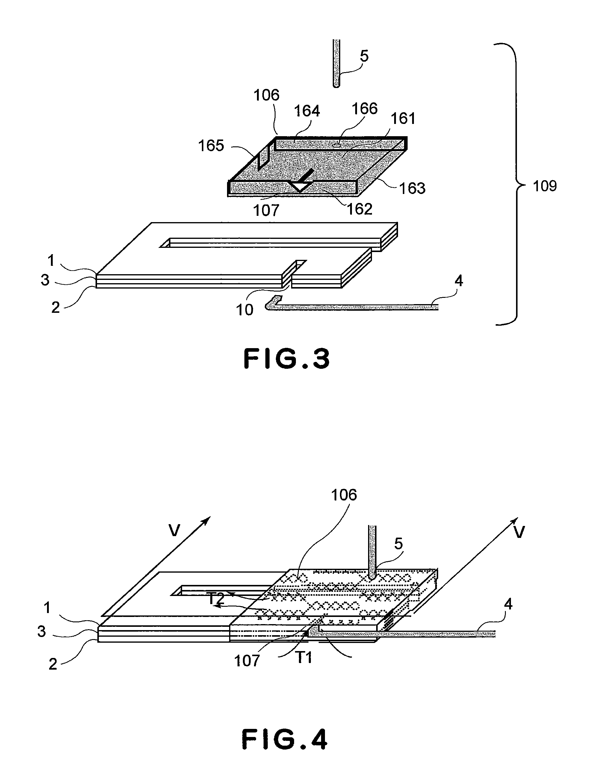
[0124]Referring to FIG. 11, the waste ink absorbing unit in this embodiment is also made up of three parallelepipedic waste ink absorbing portions stacked simply in layers, and an evaporation retarding member placed above the top ink absorbing portion with the provision of a space with a height of roughly 1 mm between the evaporation retarding member and top waste ink absorbing portion. The evaporation retarding member has two walls. The portion of the evaporation retarding member which covers the top surface of the top waste ink absorbing portion is 80% in size of the top surface of the top waste ink absorbing portion intended for absorbing the pigment-based black waste ink.

embodiment 3

[0125]Referring to FIG. 2, the waste ink absorbing unit in this embodiment is made up of three parallelepipedic waste ink absorbing portions stacked simply in layers, and an evaporation retarding member placed above the top ink absorbing portion with the provision of a space with a height of roughly 1 mm between the evaporation retarding member and top waste ink absorbing portion. The evaporation retarding member has four walls. The portion of the evaporation retarding member which covers the top surface of the top waste ink absorbing portion is 80% in size of the top surface of the top waste ink absorbing portion intended for absorbing the pigment-based black waste ink.


PUM


Abstract

A residual ink container comprising laminated members for absorbing residual ink not used for recording, wherein the laminated members are laminated with a gap between adjacent ones of the members; and a covering member covering such that non-contact portion is provided between the covering member and a topmost one of the laminated member so as not to press against the topmost one.

Description

FIELD OF THE INVENTION AND RELATED ART[0001]The present invention relates to an ink jet recording apparatus provided with a waste ink absorbing member in the form of a roughly parallelepipedic thin plate. It also relates to a waste ink storage unit which is significantly higher in ink absorbency and ink storage capacity, being therefore significantly longer in service life than a waste ink storage unit in accordance with the prior art.[0002]An ink jet recording apparatus is a recording apparatus which forms an image on a sheet of recording medium, such as ordinary paper, glossy paper, and specifically coated paper, by ejecting small droplets of ink so that they land on the sheet of recording medium. In recent years, an ink jet recording apparatus has been significantly reduced in price, and it has also been significantly increased in printing speed. Thus, the usage of an ink jet recording apparatus has been quickly spreading into various fields. Further, an ink jet recording apparat...

Claims


Application Information

Patent Timeline
Patent Type & Authority Patents(United States)
IPC IPC(8): B41J2/175
CPCB41J2/16505B41J2002/1728B41J2002/1742
Inventor ASAKI, NORIYASUKITAMURA, YUINAKANO, YASUSHI
Owner CANON KK
Learn More