

Permanent magnet air heater
a permanent magnet, air heater technology, applied in the field of space air heaters, can solve the problems of electric and fire hazards, substantial amounts of electric energy,
- Summary
- Abstract
- Description
- Claims
- Application Information
AI Technical Summary
Problems solved by technology
Method used
Image

Examples
first embodiment
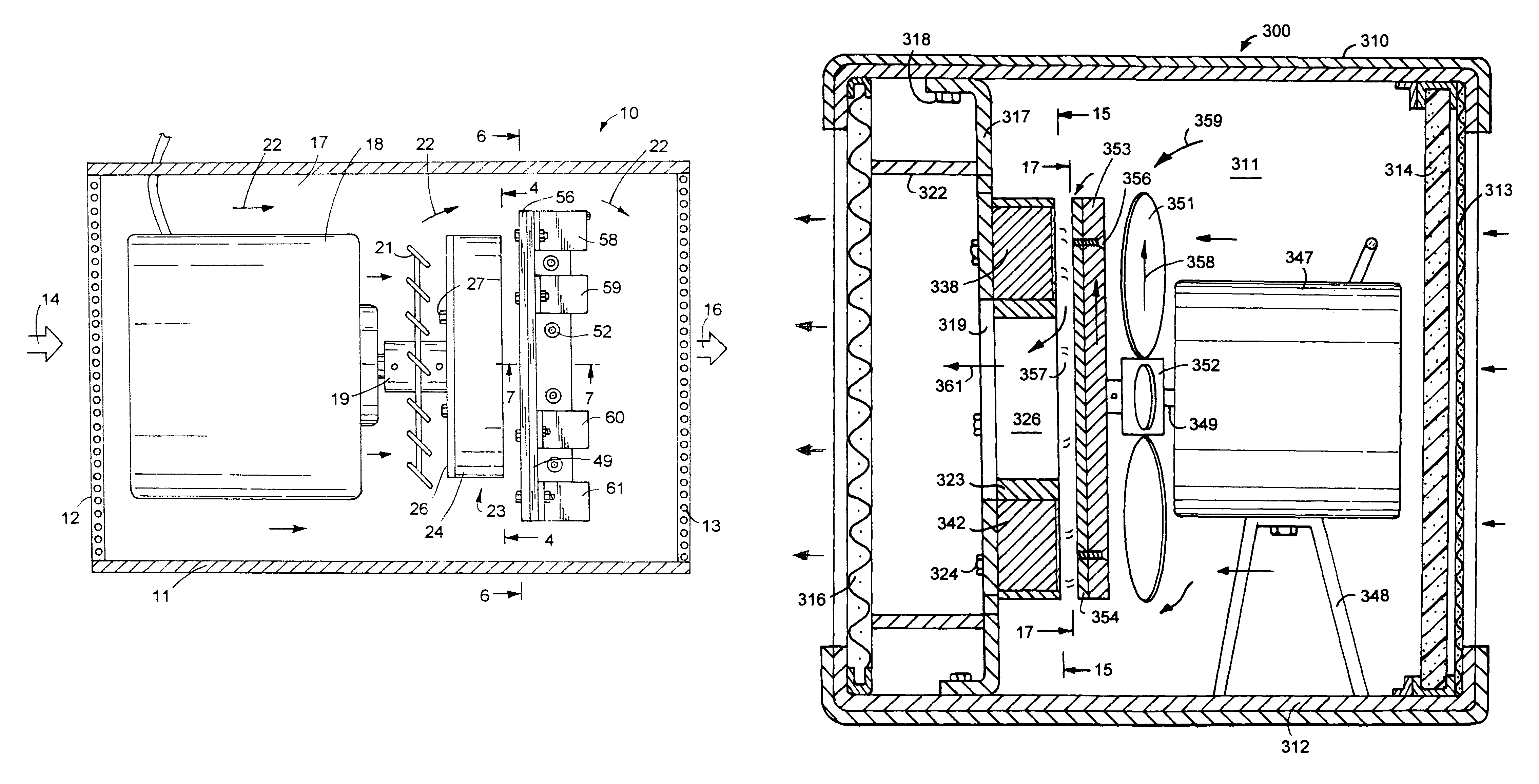
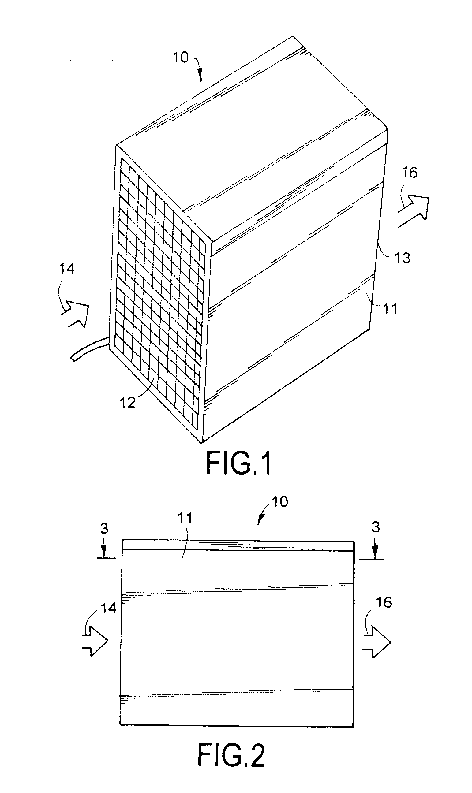
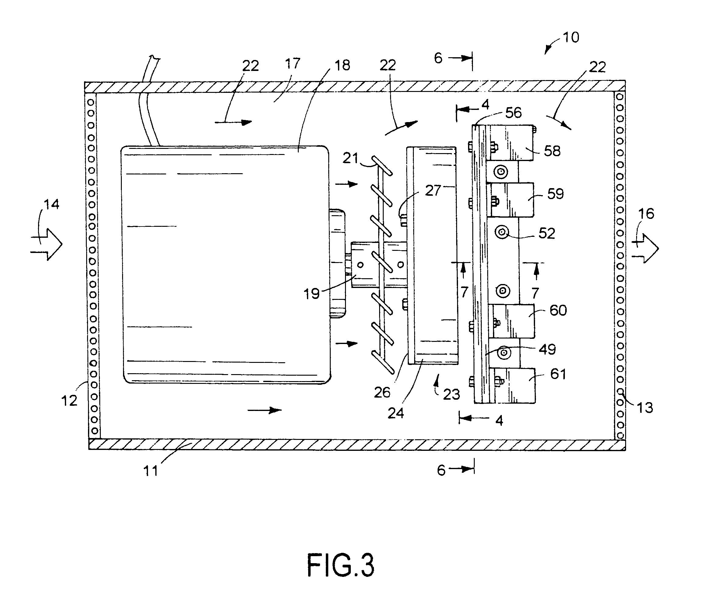
[0027]a magnet heat generator 10, shown in FIGS. 1 to 7, has a box-shaped housing 11 with open opposite ends to allow air to flow through mesh screens 12 and 13 shown by arrows 14 and 16. Screens 12 and 13 secured to opposite ends of housing 11 prevent access to the interior chamber 17 of housing 11. Screen 12 can include air filter media operable to collect dust, dirt, pollen and other airborne particulates.
[0028]An electric motor 18 located in chamber 17 and mounted on housing 11 includes a drive shaft 19 coupled to an air moving device 21 shown as a disk with blades or fan to move air shown by arrows 22 through chamber 17. Motor 18 is a prime mover which includes air and hydraulic operated motors and internal combustion engines. Other types of fans can be mounted on drive shaft 19 to move air through chamber 17. A rotor 23 mounted on drive shaft 19 adjacent air moving device 21 supports a plurality of permanent magnets 39-46 having magnetic force fields used to generate heat whic...
second embodiment
[0032]the heat generator or heater 200, shown inFIGS. 8 to 13, has a box-shaped housing 211 supported on a surface with wheels 212. A screen 213 is located across the air exit opening of housing 211. An air filter 215 extends across the air entrance opening Of housing 211. The air flowing through housing interior chamber 214 is heated and dispensed as hot air into the environment around heat generator 200.
[0033]An electric motor 216 mounted on the base of housing 211 has a drive shaft 217. A fan 218 mounted on the outer end of shaft 17 shaft 217 is rotated when motor 216 is operated to move air through chamber 214. A sleeve 219 surrounding fan 218 spaces the fan from screen 213. A rotor 221 mounted on drive shaft 217 is also rotated by motor 216. Motor 216 is a prime mover which includes but is not limited to electric motors, air motors, hydraulic operated motors and internal combustion engines. Rotor 221, shown in FIGS. 11 and 12, comprises non-ferrous or aluminum disk 226 having a...
third embodiment
[0035]the heat generator or heater 300, shown in FIGS. 14 to 17, has a box-shaped housing 310 removably mounted on a base 312. Housing 310 surrounds an interior chamber 311. A first screen 313 and air filter 314 extend across the air inlet opening to chamber 311. A second screen 316 extends across the air outlet opening of heater 300. the air flowing through interior chamber 311 is heated and dispensed as hot air into the environment around heater 300.
[0036]A primer mover 247 shown as an electric motor, is mounted on base 312 with supports 348. Supports 348 can be resilient mount members to reduce noise and vibrations. Motor drive shaft 349 supports a fan 351. The fan 351 has a hub 352 secured to shaft 349. A steel or ferrous metal disk 353 is secured to the outer end of shaft 349 adjacent fan 352. As shown in FIGS. 14 and 17, a copper absorber plate 354 is attached with fasteners 356 to steel disk 353. Copper plate 354 is located in flat surface engagement with the adjacent flat su...
PUM
 Abstract
Description
Claims
Application Information