LED lighting apparatus

a technology of led lighting and diodes, which is applied in the direction of lighting and heating apparatus, lighting support devices, fixed installations, etc., can solve the problems of long service life, short lifespan, and high power consumption, and achieve the effect of minimizing rearward light leakage, uniform light distribution, and minimizing the exposure of drivers to glar

Inactive Publication Date: 2012-10-16
PARK HO BYUNG
View PDF3 Cites 0 Cited by
  • Summary
  • Abstract
  • Description
  • Claims
  • Application Information

AI Technical Summary

Benefits of technology

[0025]According to the present invention, a Light Emitting Diode (LED) lighting apparatus using LED light sources can achieve uniform light distribution that is essential trait of a street light.
[0026]In addition to the uniform light distribution trait of a street light, the LED lighting apparatus of the present invention can minimize the exposure of a driver to glare by focusing light within a desired illuminating region while minimizing rearward light leakage, resulting in highly effective lighting. Accordingly, the LED lighting apparatus may be applied to a variety of lighting apparatuses including a safety light, a tunnel light, or a courtesy light. Extension of LED lighting to these fields provides considerable advantages both in terms of reduced power consumption and environmental impact, constituting a major advance in the field of LED lighting.

Problems solved by technology

These conventional street lights using the aforementioned light source have disadvantages, such as high power consumption and short lifespan, and therefore, a novel street light using a Light Emitting Diode (LED), which exhibits remarkably low power consumption and has a nearly indefinite lifespan, has been actively studied and developed.
However, LED street lights configured in this manner suffer from a spotlight phenomenon wherein the region immediately below the LED street light is considerably brighter than peripheral regions.
However, the above described LED street light has difficulty uniformly illuminating all of a plurality of lanes of a roadway because LEDs have a narrow view angle, or suffers from deterioration in lighting performance.
For example, if it is assumed that the above described LED street light is installed above a two-lane road having a lane width of 3.2 m, light may be unevenly distributed in a direction perpendicular to a lane as illustrated in FIG. 2, causing severe variation in per lane illuminance.

Method used


Image

  • LED lighting apparatus
  • LED lighting apparatus
  • LED lighting apparatus

Examples


Embodiment Construction

[0037]Hereinafter, the present invention will be described below in more detail with reference to the accompanying drawings.

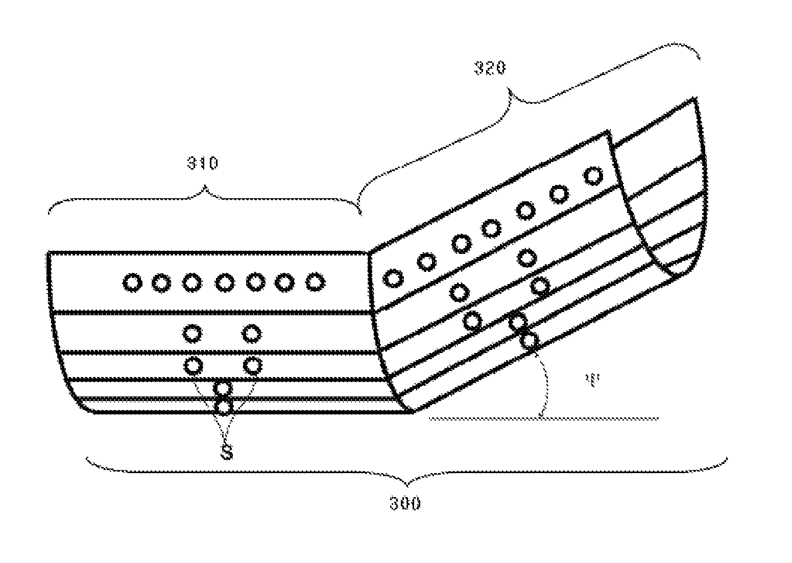
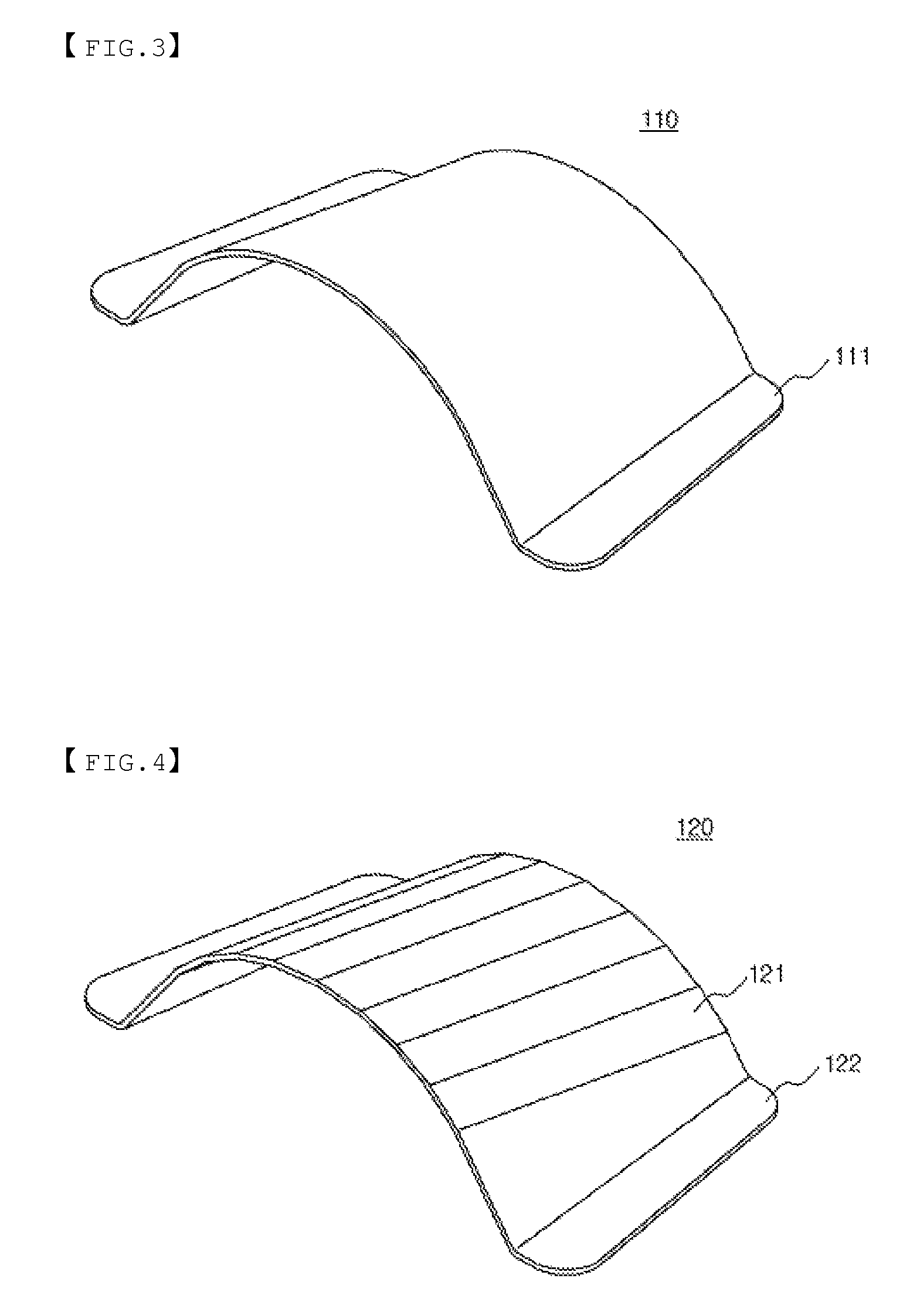
[0038]A Light Emitting Diode (LED) lighting apparatus according to the present invention, which is installed at a location where a bottom surface requires uniform illuminance or luminance distribution, includes LED lighting unit modules having a plurality of LED light sources arranged on an inner or outer curved surface of a substantially half cylinder member, wherein two or more LED lighting unit modules are arranged in a longitudinal direction of the half cylinder member.

[0039]In an exemplary embodiment of the present invention, the LED lighting unit module serves as a fundamental component, and preferably, two or more LED lighting unit modules are arranged to construct the LED lighting apparatus.

[0040]The LED lighting unit module is configured in such a manner that the LED light sources are attached to the inner or outer curved surface of the substantially h...


PUM


Abstract

The lighting device is provided with lamp housing, LED module, terminal cover, and light penetrating hood. Lamp housing comprises base, heat sink on the base, thermal dissipation channel between neighboring two heat sinks, and the base inner container. LED module comprises base for fixing, lamp cover attached to the side of the base, multiple LED lamp being inside the lamp cover, and connecting part connected to the corresponding container on the base. Each terminal cover seals the forward and reward part of the lamp housing, and the light penetrating hood is connected below the lamp housing, and the container for LED module is surrounded with the lamp housing, the terminal cover, and the light penetrating hood. This utility model can simplify the manufacturing process and cut down the cost and time to research and develop.

Description

CROSS REFERENCE TO RELATED APPLICATION[0001]This application claims the priority of Korean Patent Application No. 10-2008-0047658, filed on May 22, 2008 and Korean Patent Application No. 10-2008-0076321, filed on Aug. 5, 2008 in the KIPO (Korean Intellectual Property Office), the disclosure of which is incorporated herein in their entirety by reference. Further, this application is the National Phase application of International Application No. PCT / KR2009 / 002702, filed May 22, 2009, which designates the United States and was published in English. Each of these applications is hereby incorporated by reference in their entirety into the present application.TECHNICAL FIELD[0002]The present invention relates to a Light Emitting Diode (LED) lighting apparatus, and more particularly, to an LED lighting apparatus capable of focusing the maximum quantity of light within a desired illuminating region.BACKGROUND ART[0003]In general, a street light is a lighting apparatus which is provided to ...

Claims


Application Information

Patent Timeline
Patent Type & Authority Patents(United States)
IPC IPC(8): F21S4/00F21V21/00
CPCF21K9/00F21S2/00F21S8/086F21V19/003F21Y2101/02F21W2131/103F21Y2115/10
Inventor PARK, HO BYUNG
Owner PARK HO BYUNG
Why Eureka
Try Eureka