Methods for driving electro-optic displays

a technology of electrooptic displays and drives, applied in the direction of liquid crystal compositions, instruments, chemistry apparatuses and processes, etc., can solve the problems of preventing their widespread use, inadequate service life of these displays, and gas-based electrophoretic media being susceptible to the same types of problems, so as to facilitate the transition to the second drive scheme

Active Publication Date: 2012-10-16
E INK CORPORATION
View PDF213 Cites 260 Cited by
  • Summary
  • Abstract
  • Description
  • Claims
  • Application Information

AI Technical Summary

Problems solved by technology

Nevertheless, problems with the long-term image quality of these displays have prevented their widespread usage.
For example, particles that make up electrophoretic displays tend to settle, resulting in inadequate service-life for these displays.
Such gas-based electrophoretic media appear to be susceptible to the same types of problems due to particle settling as liquid-based electrophoretic media, when the media are used in an orientation which permits such settling, for example in a sign where the medium is disposed in a vertical plane.
Indeed, particle settling appears to be a more serious problem in gas-based electrophoretic media than in liquid-based ones, since the lower viscosity of gaseous suspending fluids as compared with liquid ones allows more rapid settling of the electrophoretic particles.
In addition, many current display controllers can only make use of one updating scheme at any given time.
As a result, the display is not responsive enough to react to rapid user input, such as keyboard input or scrolling of a select bar.
This limits the applicability of the display for interactive applications.

Method used


Image

  • Methods for driving electro-optic displays
  • Methods for driving electro-optic displays
  • Methods for driving electro-optic displays

Examples


Embodiment Construction

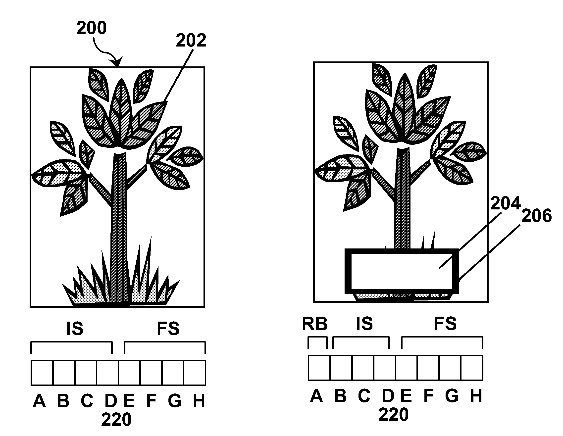
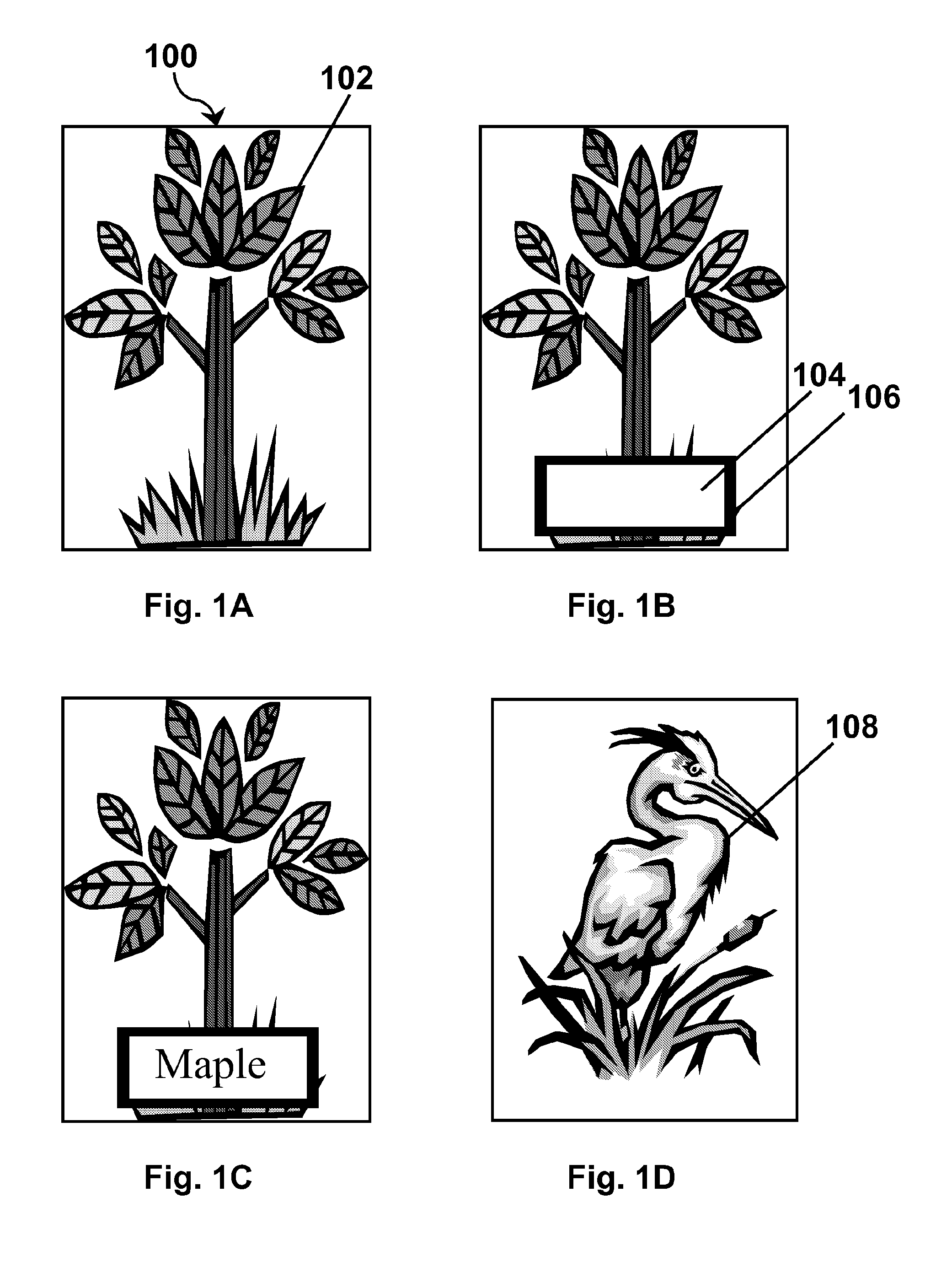
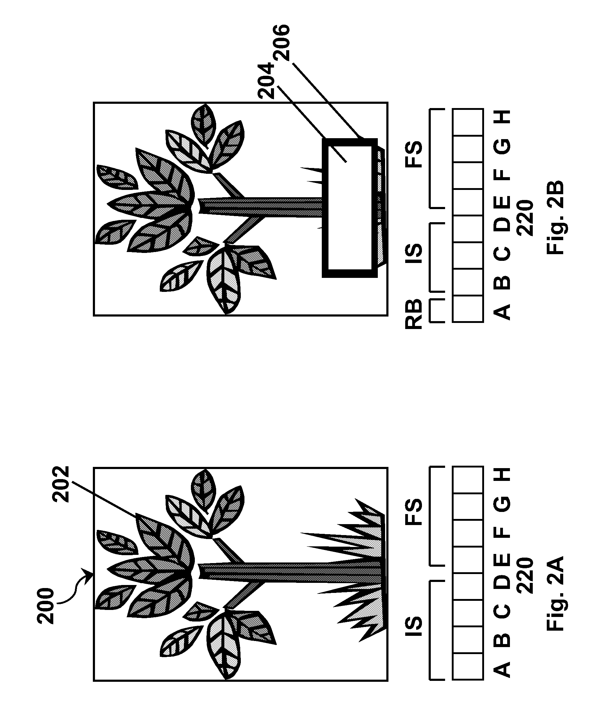
[0054]As already mentioned, this invention provides a method for updating a bistable electro-optic display using two different drive schemes. An image is written on the display using a first drive scheme capable of driving pixels to three (or typically more) different display states; and thereafter the image is varied using a second drive scheme, which makes use of only two gray levels, at least one of which is not an extreme optical state of the pixel.

[0055]As explained in more detail below, the present driving method is designed to provide a first drive scheme which can render gray scale images, while allowing for a more rapid drive scheme which is useful when it is necessary that the image respond quickly to user or other input. Experience with gray scale drive schemes shows that in such drive schemes some transitions can be effected more quickly than others and, of course, the overall transition time for an image change must be at least as long as the longest of the transitions ...


PUM


Abstract

A bistable electro-optic display is updated by writing an image on the display using a first drive scheme capable of driving pixels to multiple gray levels, and thereafter varied using a second drive scheme using only two gray levels, at least one of which is not an extreme optical state of the pixel.

Description

REFERENCE TO RELATED APPLICATIONS[0001]This application is a continuation-in-part of application Ser. No. 11 / 425,408, filed Jun. 21, 2006 (Publication No. 2006 / 0232531), now U.S. Pat. No. 7,733,311), which in turn in a divisional of application Ser. No. 10 / 814,205, filed Mar. 31, 2004 (now U.S. Pat. No. 7,119,772). This application also claims benefit of copending Application Ser. No. 60 / 864,904, filed Nov. 8, 2006.[0002]This application is also related to:[0003](a) U.S. Pat. No. 6,504,524;[0004](b) U.S. Pat. No. 6,512,354;[0005](c) U.S. Pat. No. 6,531,997;[0006](d) U.S. Pat. No. 6,995,550;[0007](e) U.S. Pat. No. 7,012,600, and the related Applications Publication Nos. 2005 / 0219184 (now U.S. Pat. No. 7,312,794); 2006 / 0139310(now U.S. Pat. No. 7,733,335); and 2006 / 0139311 (now U.S. Pat. No. 7,688,297);[0008](f) U.S. Pat. No. 7,034,783;[0009](g) U.S. Pat. No. 7,193,625, and the related Application Publication No. 2007 / 0091418;[0010](h) U.S. Pat. No. 7,259,744;[0011](i) application Ser...

Claims


Application Information

Patent Timeline
Patent Type & Authority Patents(United States)
IPC IPC(8): G09G3/36
CPCG09G3/2011G09G3/344G09G2310/04
Inventor ZEHNER, ROBERT W.AMUNDSON, KARL R.SJODIN, THEODORE A.GATES, HOLLY G.
Owner E INK CORPORATION
Why Eureka
Try Eureka