Stool assembly

Inactive Publication Date: 2012-10-23
HYGH EDMUND
View PDF25 Cites 5 Cited by
  • Summary
  • Abstract
  • Description
  • Claims
  • Application Information

AI Technical Summary

Problems solved by technology

The rotational element of such stools are usually simple devices that may or may not have some type of bearing element and because of structural simplicity may be prone t

Method used


Image

  • Stool assembly
  • Stool assembly
  • Stool assembly

Examples


Embodiment Construction

[0010]The following detailed description represents the best currently contemplated modes for carrying out the invention. The description is not to be taken in a limiting sense, but is made merely for the purpose of illustrating the general principles of the invention.

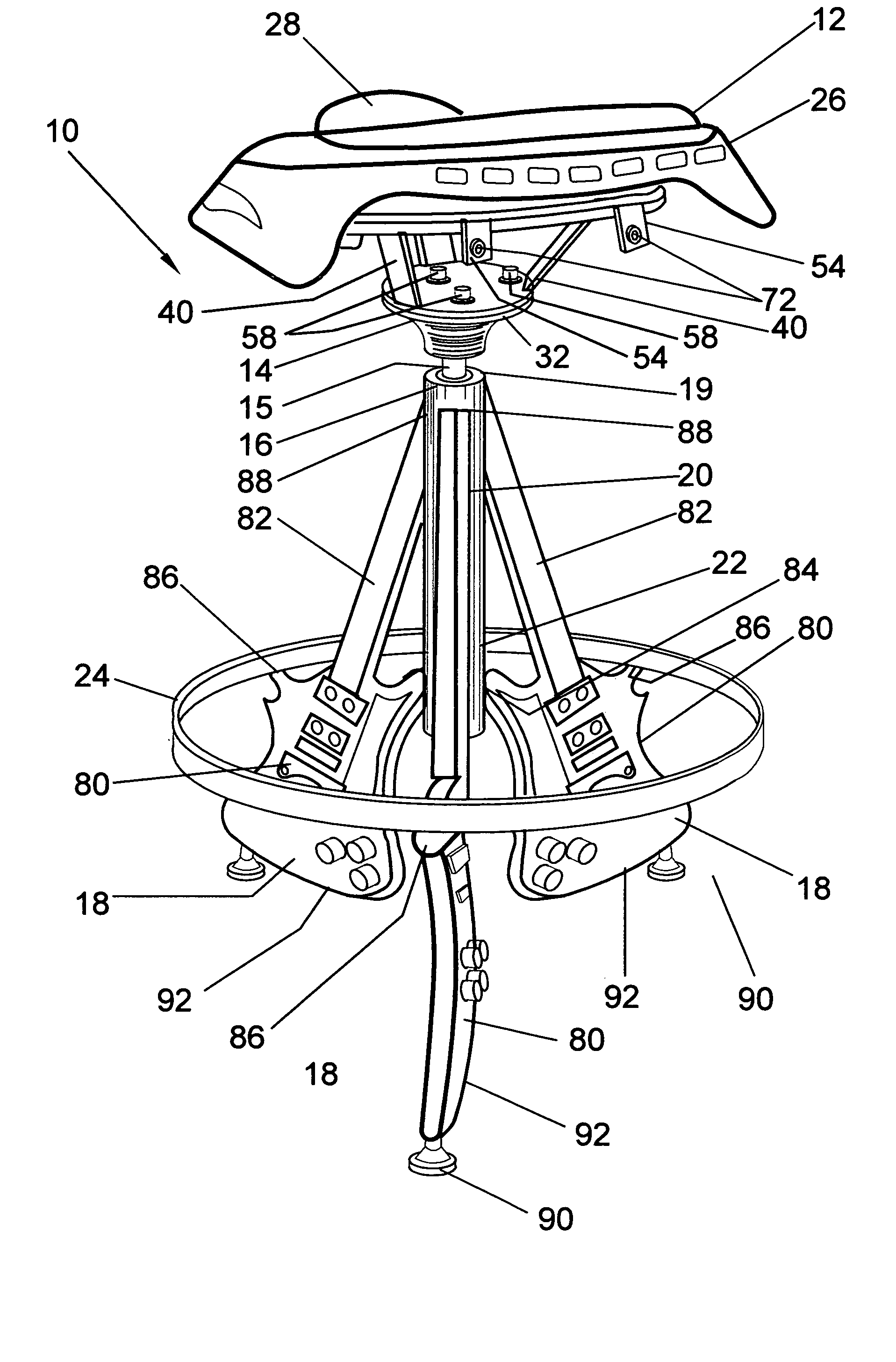
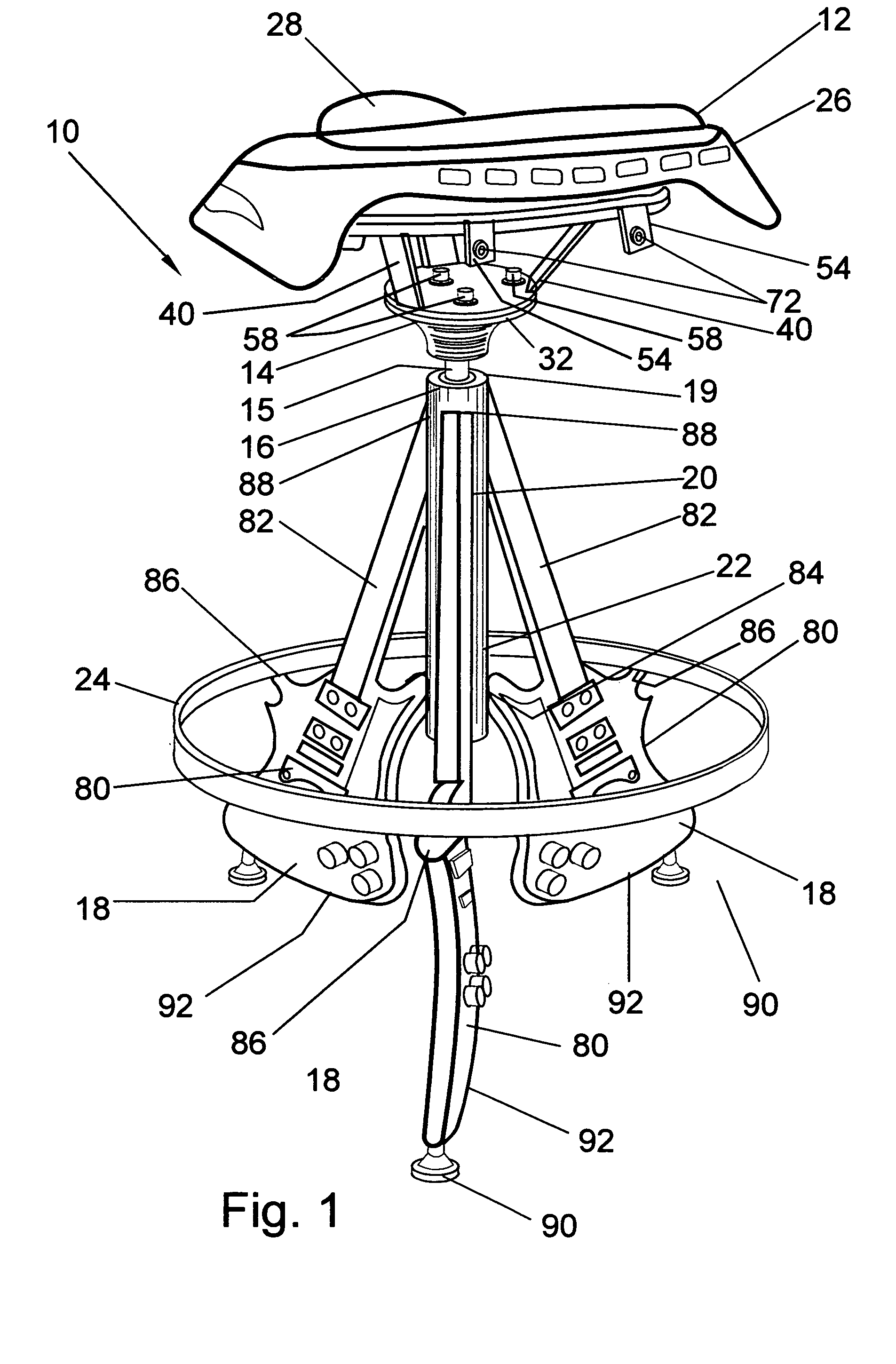
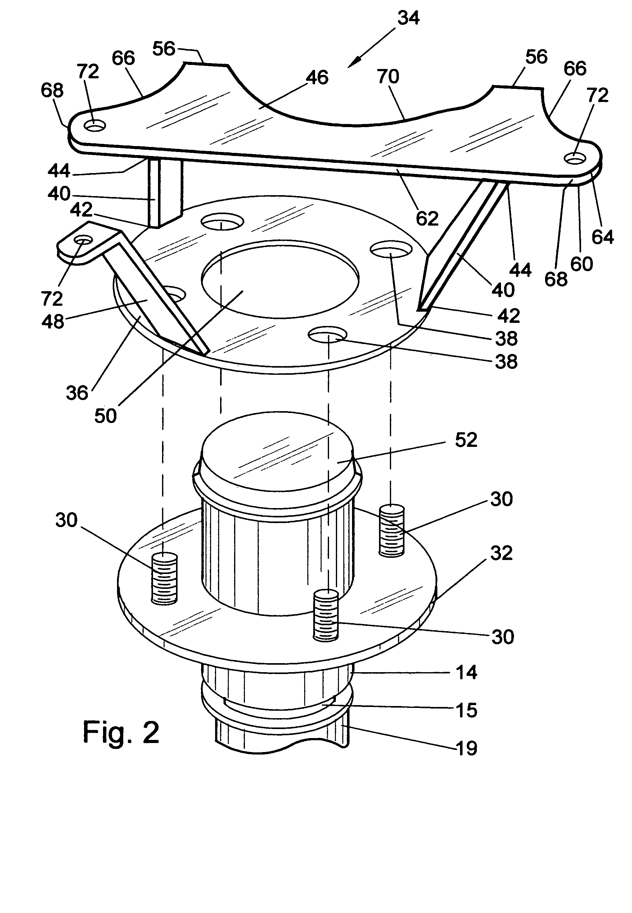
[0011]Referring to FIGS. 1 through 4, a stool 10 may have a seat 12 attached to a bracket 34 that is attached to a rotatable seat element 14 that has a central shaft 15 that is attached at a top end 19 of a central pedestal 16 that may have three or more legs 18 attached to a middle portion 20 and bottom portion 22 of the pedestal 16. The legs 18 may be splayed outwardly and equidistantly in a radial sense. A generally annular footrest 24 may be arranged around the pedestal 16 and may be attached to each of the legs 18.

[0012]The rotatable seat element 14 may be a wheel hub structure and the drawings illustrate a trailer vehicle hub that typically has four mounting bolts 30. A trailer vehicle hub may be a relatively rig...


PUM


Abstract

The present invention may be used for attachment of a variety of seats and legs. A bracket may have a generally circular metal plate with bolt holes for receipt of bolts of a rotatable seat element. A seat mounting plate may be positioned above the circular metal plate on a support beam. The rotatable seat element may be attached by the bolts and fasteners to the bracket and to the top of a central pedestal by a central shaft. A plurality of legs may be attached to a middle portion and a bottom portion of the central pedestal. A generally annular footrest may be arranged around the central pedestal and attached to a second edge of the legs that are splayed outwardly and generally equidistant radially from the central pedestal.

Description

BACKGROUND OF THE INVENTION[0001]This invention relates to stools that may be used for multiple purposes such as sitting at a bar, food counter, or elevated eating surfaces, sitting at a work table or desk, or at like generally horizontal platforms. The new stool is structured for attachment of a variety of seats and legs.[0002]Stools may be known that swivel or rotate the seat element. The rotational element of such stools are usually simple devices that may or may not have some type of bearing element and because of structural simplicity may be prone to failure. Often the seat of a stool has a round rod attached to the bottom of the seat frame and the rod is inserted into a sleeve or cylinder to allow rotation. Stool structures may not have brackets designed for mounting a variety of seat shapes as for example a saddle seat of a motorcycle. There may also be stools that have artistic designed legs; however, the stool structure may not allow use of a variety of leg designs when ass...

Claims


Application Information

Patent Timeline
IPC IPC(8): A47C3/18A63G9/10
CPCA47C7/002A47C9/08
Inventor HYGH, EDMUND
Owner HYGH EDMUND
Why Eureka
Try Eureka