Supercharge Your Innovation With Domain-Expert AI Agents!

Image correction device and image correction method thereof

a technology of image correction device and image sensor, which is applied in the field of image correction device and image correction method, can solve the problems of inaccurate test (e.g., the test of resolution) deteriorating the imaging quality of the camera module, and affecting the accuracy of the alignment of the lens module and the image sensor

Inactive Publication Date: 2012-10-23
HON HAI PRECISION IND CO LTD
View PDF6 Cites 2 Cited by
  • Summary
  • Abstract
  • Description
  • Claims
  • Application Information

AI Technical Summary

Problems solved by technology

The lens module and the image sensor may not be aligned accurately.
The deviation may render the test (e.g., the test of resolution) of the camera module inaccurately.
In addition, the deviation may deteriorate the imaging quality of the camera module.

Method used


Image

  • Image correction device and image correction method thereof
  • Image correction device and image correction method thereof
  • Image correction device and image correction method thereof

Examples


Embodiment Construction

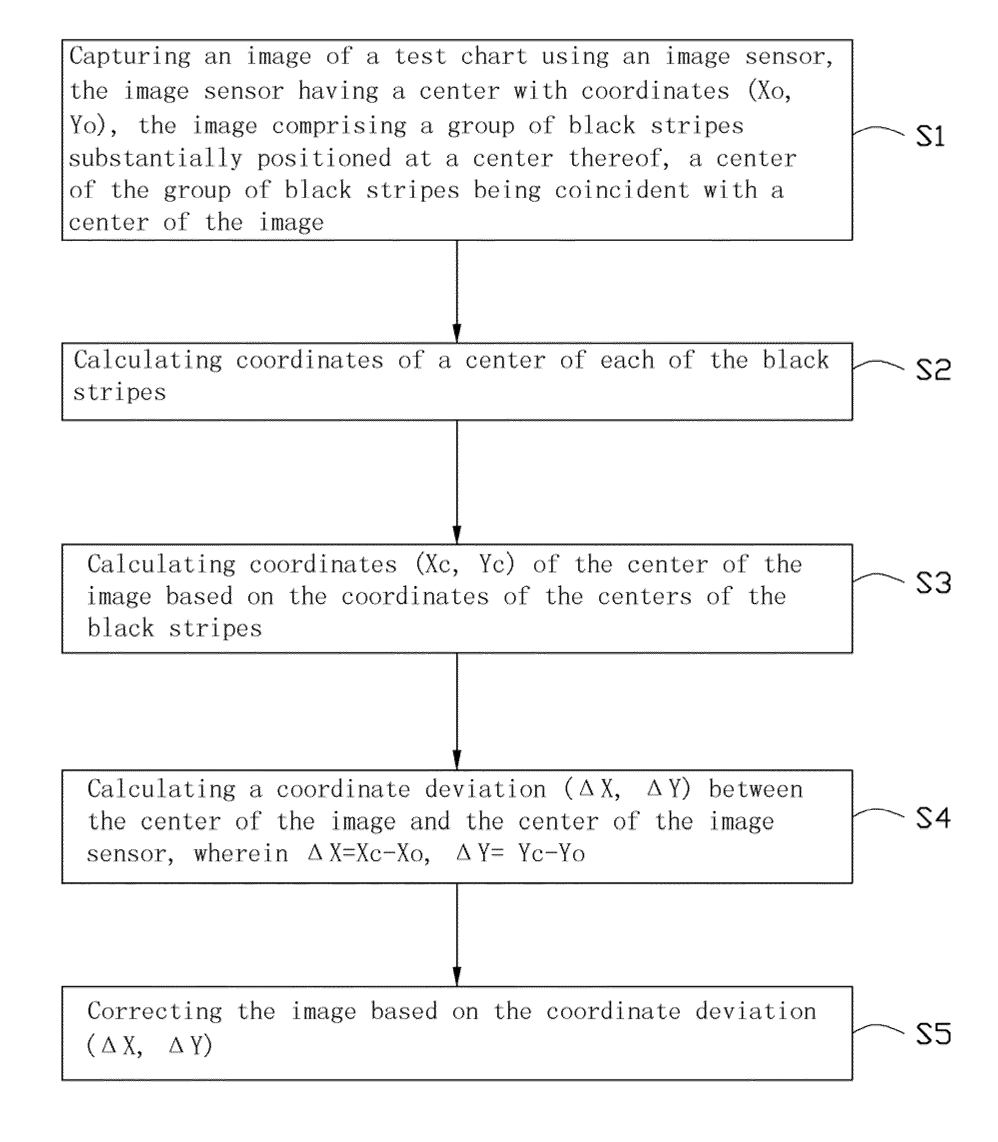
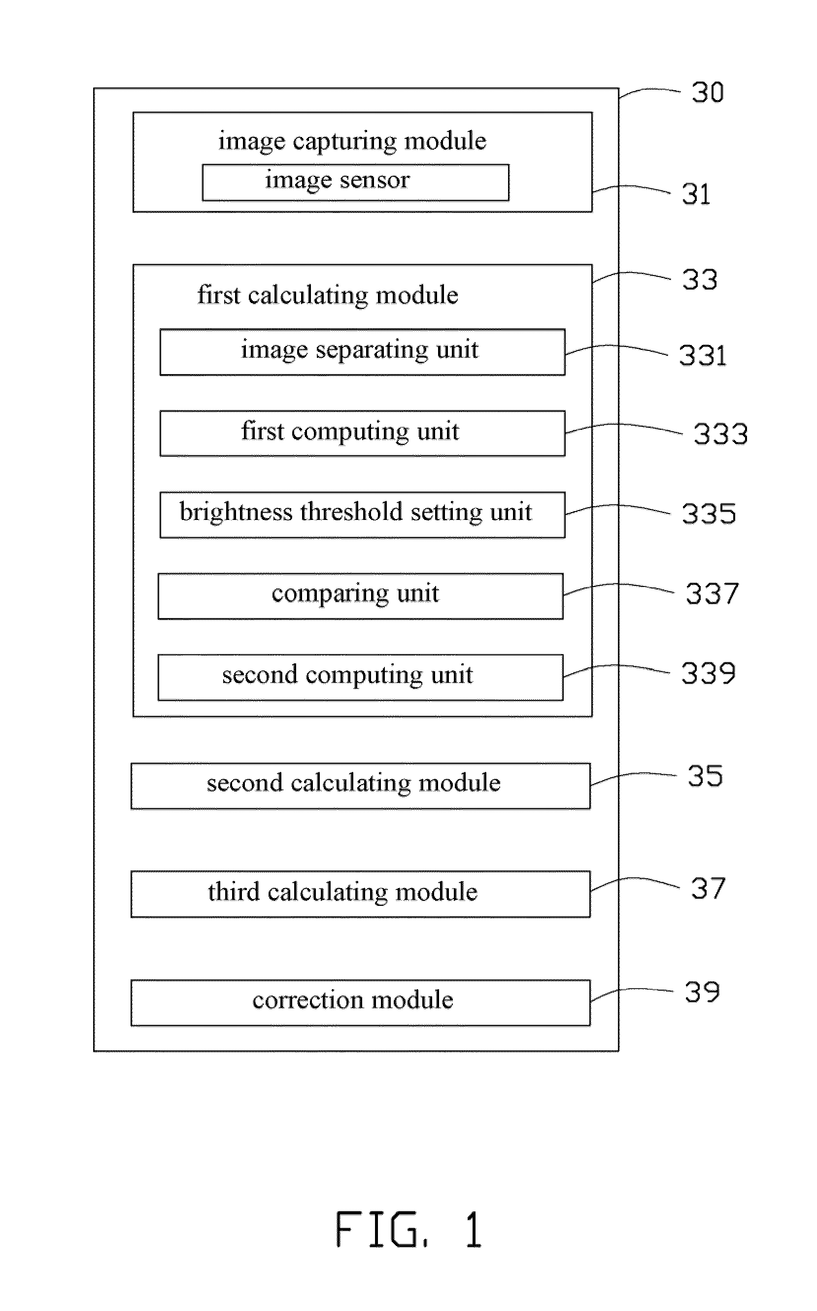
[0010]Referring to FIG. 1, an image correction device 30 according to an exemplary embodiment is shown. The image correction device 30 includes an image capturing module 31, a first calculating module 33, a second calculating module 35, and a third calculating module 37, and a correction module 39.

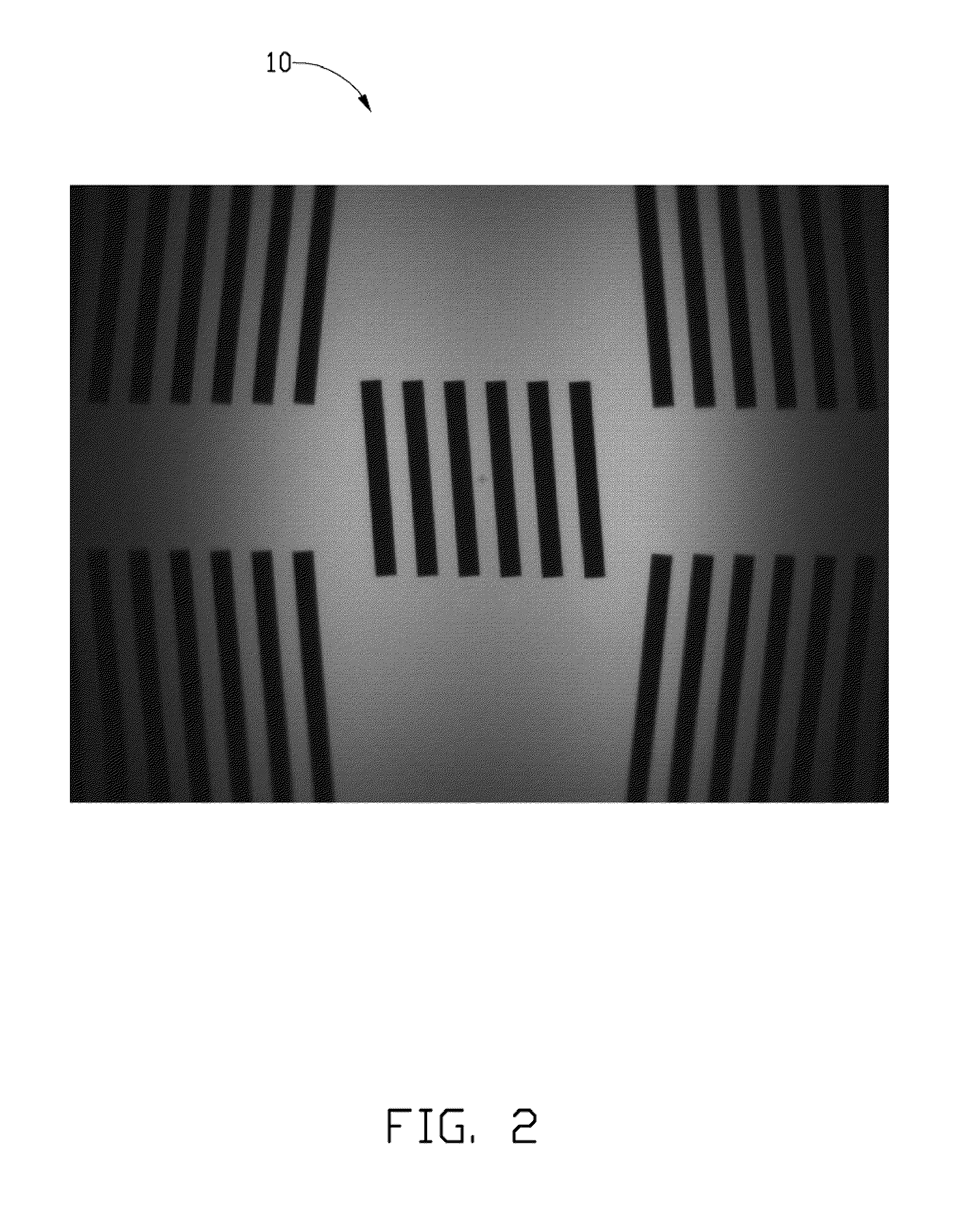
[0011]The image capturing module 31 includes an image sensor 311 with a center. Coordinates of the center of the image sensor 311 are represented by (Xo, Yo). The image capturing module 31 is configured (i.e., structured and arranged) for taking an image 20 of a test chart 10, as seen in FIGS. 2-3. In the present embodiment, the image capturing module 31 is a video graphics array (VGA) camera module.

[0012]In the present embodiment, the test chart 10 is a substantially rectangular monochromatic picture. The test chart 10 includes one group of black stripes positioned in the middle thereof and four groups of black stripes respectively positioned in four corners. Each group of black stripes i...


PUM


Abstract

An image correction device includes an image capturing module, a first calculating module, a second calculating module, a third calculating module, and a correction module. The image capturing module includes an image sensor having a center (Xo, Yo). The image capturing module takes an image of a test chart. A center of the group of black stripes is coincident with a center of the image. The first calculating module is for calculating coordinates of a center of each black stripe of the group of black stripes. The second calculating module is for calculating coordinates (Xc, Yc) of the center of the image. The third calculating module is for calculating a coordinate deviation (ΔX, ΔY)=(Xc−Xo, Yc−Yo). The correction module is for inputting the coordinate deviation (ΔX, ΔY) into the image sensor so that the image sensor corrects the image according to the coordinate deviation (ΔX, ΔY).

Description

BACKGROUND[0001]1. Technical Field[0002]The present disclosure relates to an image correction device and an image correction method for the image correction device.[0003]2. Description of Related Art[0004]A typical camera module includes a lens module and an image sensor. The lens module and the image sensor may not be aligned accurately. A center of an image taken by the camera module may deviate from a center of the image sensor. The deviation may render the test (e.g., the test of resolution) of the camera module inaccurately. In addition, the deviation may deteriorate the imaging quality of the camera module.[0005]Therefore, it is desirable to provide an image correction device and an image correction method, which can overcome the above-mentioned limitations.BRIEF DESCRIPTION OF THE DRAWINGS[0006]FIG. 1 is a block diagram of an image correction device according to an embodiment.[0007]FIG. 2 is a plane view of a test chart according to one embodiment.[0008]FIG. 3 shows an image ...

Claims


Application Information

Patent Timeline
Patent Type & Authority Patents(United States)
IPC IPC(8): H04N17/00
CPCH04N17/002
Inventor NING, WEN-MIN
Owner HON HAI PRECISION IND CO LTD
Features
  • R&D
  • Intellectual Property
  • Life Sciences
  • Materials
  • Tech Scout
  • Unparalleled Data Quality
  • Higher Quality Content
  • 60% Fewer Hallucinations
Learn More