Method for hydroforming and hydroformed product

a technology of hydroforming and product, applied in the field of hydroforming and hydroforming products, can solve the problems of plurality of hydroforming steps or separate punches able to move in the mold, and the difficulty of applying to complicated cross-sections, etc., to achieve the effect of raising the yield of the hydroforming produ

Active Publication Date: 2012-10-30
NIPPON STEEL CORP
View PDF22 Cites 88 Cited by
  • Summary
  • Abstract
  • Description
  • Claims
  • Application Information

AI Technical Summary

Benefits of technology

[0014]In the present invention, the object is to raise the yield of the hydroformed product by forming even the tube ends to the product shape as much as possible. Further, the inventors propose a hydroformed product having a flange along its entire length in the longitudinal direction formed by a single step.

Problems solved by technology

Application to complicated cross-sections is considered difficult.
On the other hand, hydroforming has the defect of the difficulty of spot welding and bolting with other parts after shaping.
However, with these methods, pluralities of hydroforming steps or separate punches able to move in the mold become necessary.
Further, with the method, it is believed difficult to form a flange along the entire length while applying internal pressure.

Method used


Image

  • Method for hydroforming and hydroformed product
  • Method for hydroforming and hydroformed product
  • Method for hydroforming and hydroformed product

Examples


example 1

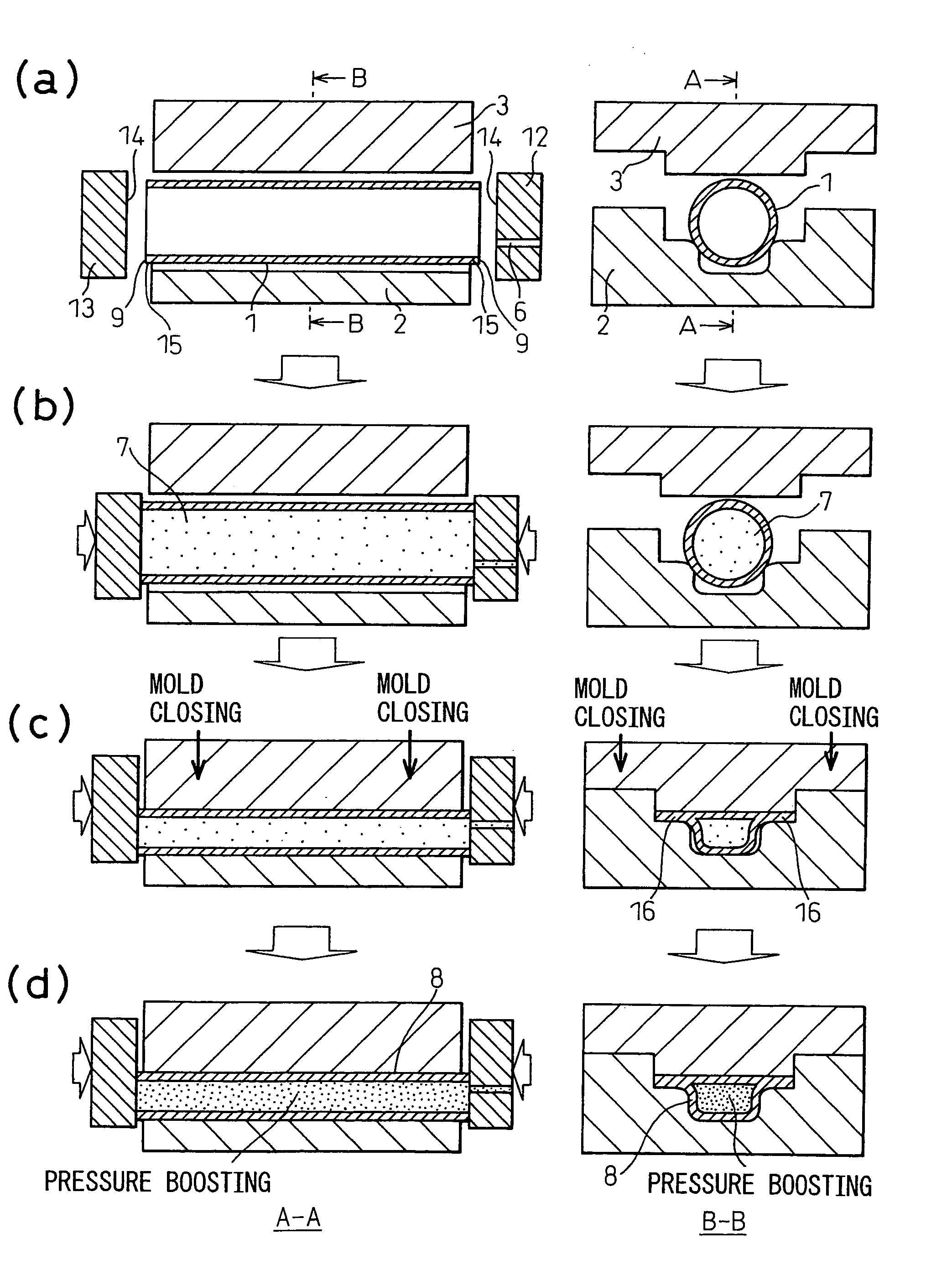
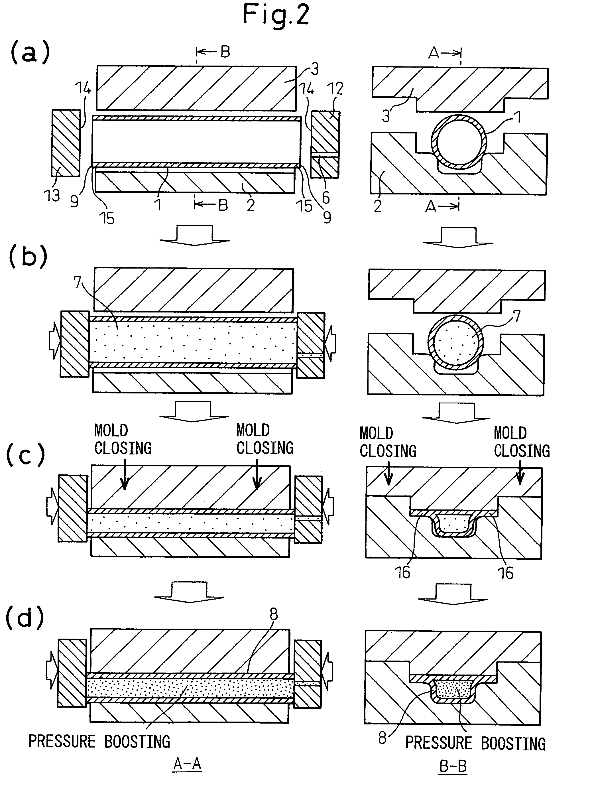
[0077]For the tube material, a steel tube having an outside diameter of 60.5 mm, a wall thickness of 2.5 mm, and a total length of 370 mm was used. For the steel type, STKM13B of a steel tube made of carbon steel for machine structures was employed. The hydroforming mold had a cross-sectional shape across the entire length as shown in FIG. 7, a length of 360 mm, and a straight shape. Accordingly, the seal length Ls in this case was 5 mm (=(370−360) / 2) or two times the plate thickness of 2.5 mm. Further, the front ends of the seal punches were made 120×120 mm flat square shapes. For the material, SKD61 was employed. The surface hardness was made a Rockwell hardness of HRC54 to 57. The surface roughness of the front ends was made about Ra 1.6. The above tube materials and molds were used for hydroforming.

[0078]As the hydroforming conditions, the internal pressure P1 at the time of closing the mold was made 10 MPa and the pressing force F1 was made 100,000 N. Due to the size of the ste...

example 2

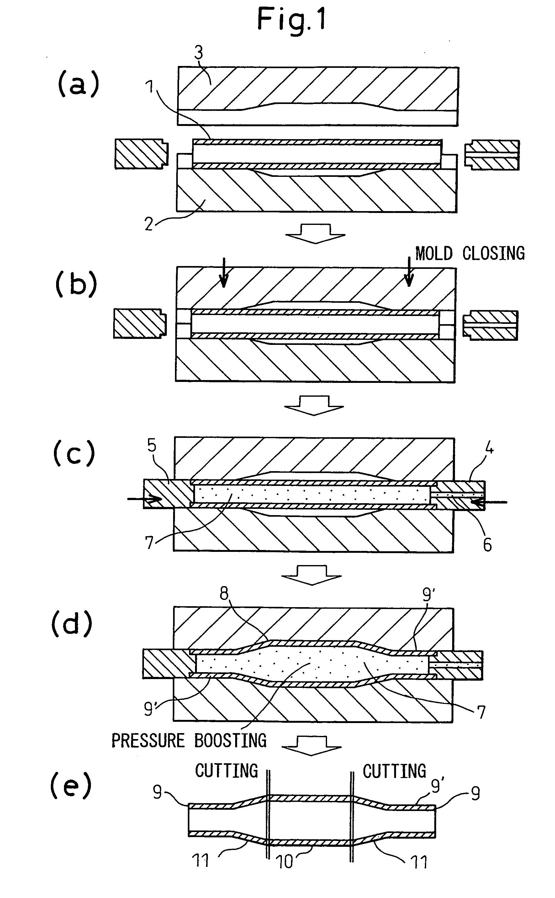
[0088]FIG. 8 shows a lower mold 17 for forming a flange in the case of a bent shape. Note that the cross-sectional shape of the groove of the mold cavity is the same as in FIG. 5 and has a flange part at the two sides along the entire length. The radius of curvature is 2.07×10⁻¹ (=1 / 484) (1 / mm) along the entire length in the longitudinal direction. For the tube material, a STKM13B steel tube of an outside diameter of 60.5 mm, a wall thickness of 2.5 mm, and a total length of 370 mm the same as Example 1 was used.

[0089]First, the center of the tube material was bent by ram bending to a radius of curvature of 484 mm (=8 times the outside diameter of the tube material). This bent tube was placed to the groove of the lower mold 17 of FIG. 8. The distance between the mold ends in the middle of the groove was 360 mm, so if placing a 370 mm length tube material, it will stick out from the mold ends by 5 mm each. Accordingly, a seal length LS of Example 2 of 2 times the plate thickness of 2...


PUM


Abstract

The object is to raise the yield by greatly eliminating the disposed amounts of the tube ends, prevent wrinkles due to closing the mold while applying internal pressure, cutting the plurality of steps of hydroforming and pre-processing of the tube ends, cutting the mold costs by simplifying the mold mechanism, and obtaining a hydroformed product formed with a flange along its entire length.For this reason, the present invention provides a hydroforming method which places a metal tube to a lower mold in the state with the tube ends sticking out from it and injects a pressurizing fluid into the metal tube through the inside of a seal punch and gradually presses seal punches against tube ends of the metal tube to apply a predetermined pressing force and fill the inside of the metal tube with the pressurizing fluid to apply a predetermined internal pressure, next, in the state with the internal pressure and pressing force applied, lowers the upper mold and closes the mold so as to deform the tube and end the processing in the state with the tube ends sticking out from the mold, and, further, boosting the internal pressure in the metal tube after closing the mold and ending the forming operation and a hydroformed product processed using these methods and having a flange across the entire length in the longitudinal direction.

Description

[0001]This application is a national stage application of International Application No. PCT / JP2008 / 063469, filed 18 Jul. 2008, which claims priority to Japanese Application No. 2007-189235, filed 20 Jul. 2007, which is incorporated by reference in its entirety.TECHNICAL FIELD[0002]The present invention relates to a hydroforming method comprising placing a metal tube in a mold, closing the mold, then applying internal pressure inside the tube to form it to a predetermined shape and a hydroformed product formed by this.BACKGROUND ART[0003]The general processing steps in conventional hydroforming will be explained below using FIG. 1.[0004]First, a metal tube 1 shorter in length than the mold is placed inside a groove of the lower mold 2 so that the tube ends of the metal tube 1 are positioned inside from the end faces of the mold (same figure (a)).[0005]The metal tube 1 of this example is an example of a straight tube. In the case of a bent tube, it is necessary to perform the bending ...

Claims


Application Information

Patent Timeline
Patent Type & Authority Patents(United States)
IPC IPC(8): B21D9/15B21D26/02B21D26/041B21D26/043
CPCB21D22/025B21D26/033B21D26/043B21D26/041Y10T29/49805
Inventor MIZUMURA, MASAAKISATO, KOICHIKURIYAMA, YUKIHISA
Owner NIPPON STEEL CORP
Why Eureka
Try Eureka