

Optical testing apparatus and testing method thereof
a technology of optical testing and optical modules, applied in the field of optical testing apparatuses, can solve the problems of affecting the image quality of the imaging module,
- Summary
- Abstract
- Description
- Claims
- Application Information
AI Technical Summary
Benefits of technology
Problems solved by technology
Method used
Image

Examples
Embodiment Construction
[0009]Optical testing apparatuses according to the embodiments can be adjusted from a normal temperature to a higher temperature, and can test the working property of the components of an imaging module for electronic devices at temperature higher than ambient temperature. The higher temperature may be selected from a temperature range such as from about 40° C. to about 60° C. The normal temperature may be selected from a temperature range such as from about 20° C. to about 40° C.
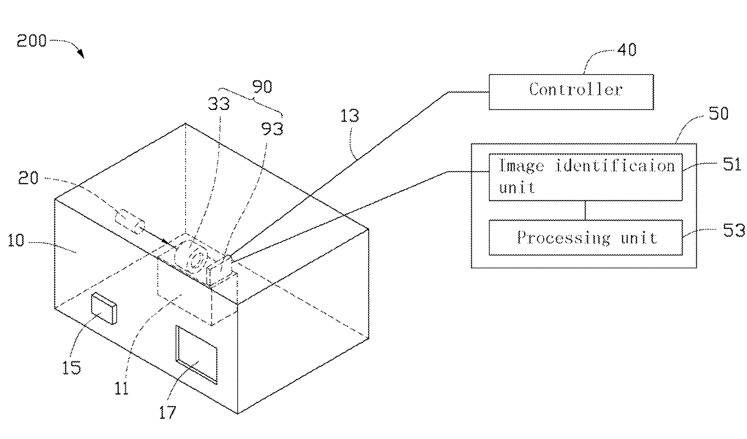
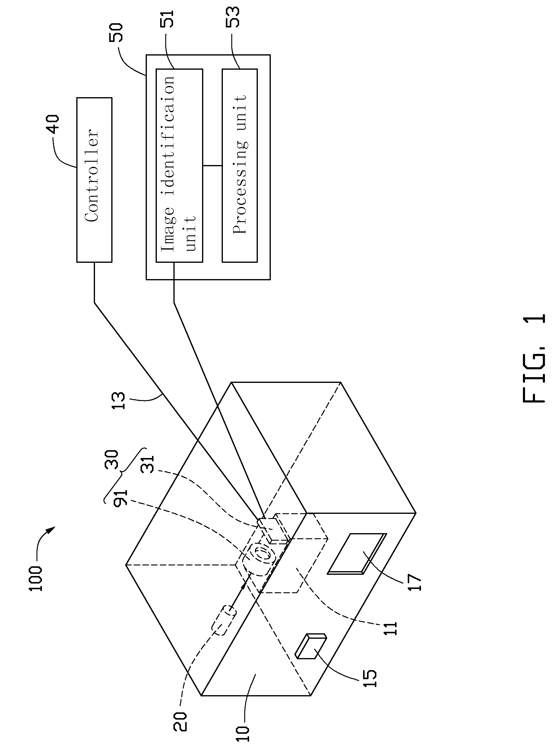
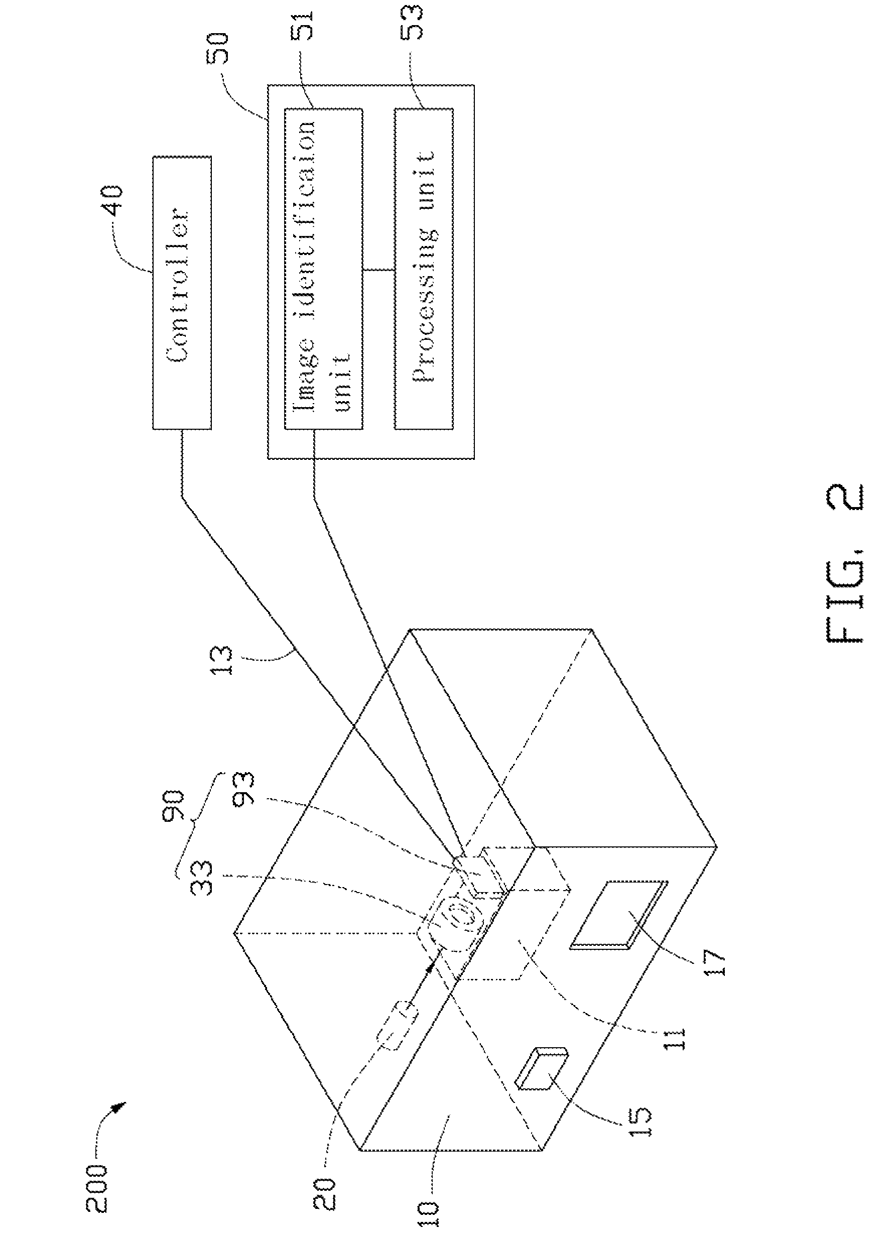
[0010]FIG. 1 shows an optical testing apparatus 100 according to a first embodiment for testing the working property of a lens module 91 of the imaging module 30 at a higher than ambient temperature. The optical testing apparatus includes a temperature control device 10, a projector 20, an image sensor 31, a controller 40, and a processor 50. The temperature control device 10 receives the lens module 91 for creating a simulated higher than ambient temperature. As for the lens module 91, the simulated enviro...
PUM
| Property | Measurement | Unit |
|---|---|---|
| temperature | aaaaa | aaaaa |
| temperature | aaaaa | aaaaa |
| optical testing | aaaaa | aaaaa |
Abstract
Description
Claims
Application Information