
Slide assembly

a technology of sliding assembly and assembly plate, which is applied in the direction of supporting structure mounting, mechanical equipment, furniture parts, etc., can solve the problems of insufficient support for the inner rail, easy twisting of the suspended terminal, and serious sloping of the cable management arm, so as to achieve stable and safer support

Active Publication Date: 2012-11-06
KING SLIDE WORKS CO LTD
View PDF10 Cites 17 Cited by
  • Summary
  • Abstract
  • Description
  • Claims
  • Application Information

AI Technical Summary

Benefits of technology

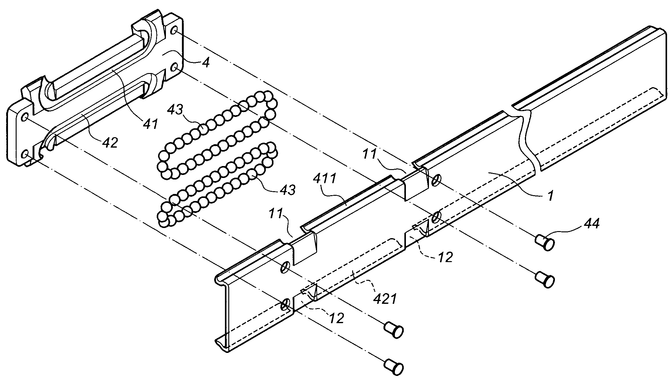
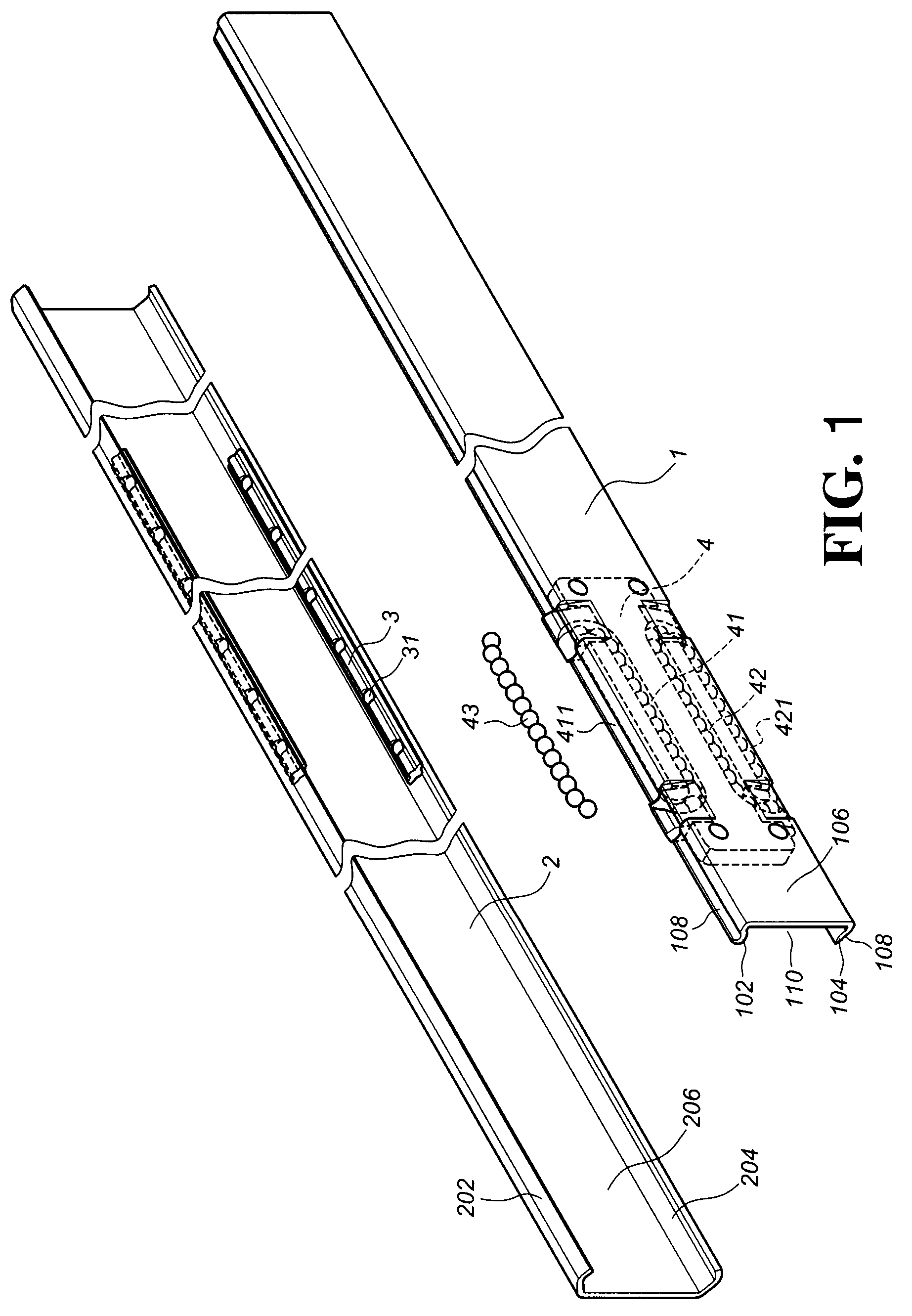
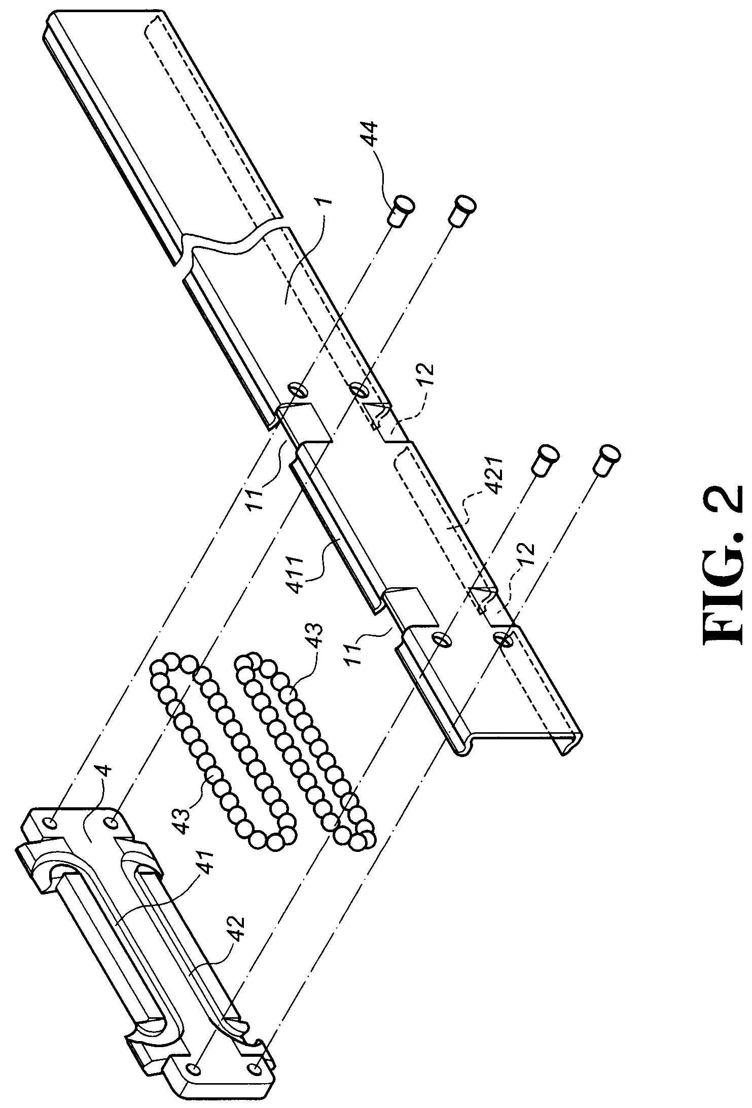
The present invention provides a slide assembly for a foldable cable management arm that improves support when the inner rail is fully retracted or sliding in relation to the outer rail. The slide assembly includes an inner rail and an outer rail, with a ball bearing carrier fixed on the inner rail. The ball bearing carrier has upper and lower ball receiving channels that define a circulating channel and an open section located in use facing the outer rail. The open section is a section of the ball receiving groove of the inner rail near the end of the inner rail. The slide assembly also includes a front brace and a rear brace that secure the cable management arm to the inner and outer rails, respectively. Overall, the slide assembly provides a more steady and safe support for the cable management arm.

Problems solved by technology

Accordingly, the suspended terminal is vulnerable to twisting.
Thus, when a front brace of a cable management arm is linked to the end of the inner rail, there is insufficient support for the inner rail where it is linked to the brace.
This results in serious sloping of the cable management arm.
This would compromise the requirement for a firm support at the location where the cable management arm (D) is connected to the inner rail (A) and would cause the cable management arm (D) to slope.
If the cable management arm (D) comprises upper and lower arms (D), this sloping of the cable management arm (D) will interfere with a drawer or similar object associated with the slide assembly or the lower cable management arm (D).

Method used


Image

  • Slide assembly
  • Slide assembly
  • Slide assembly

Examples


Embodiment Construction

[0025]Referring to FIGS. 1, 2, and 3, a first preferred embodiment of the present invention comprises a two-section slide assembly containing an inner rail (1) and an outer rail (2). The inner rail (1) is slidable in the outer rail (2) by means of multiple inner ball bearings (31), an inner ball bearing carrier (3), and a ball bearing carrier (4) disposed on the inner rail (1). The inner rail (1) has a substantially C-shaped cross-section and comprises an upper wall (102), a lower wall (104), and a side wall (106) extending between the upper and the lower walls (102, 104). Each of the upper and the lower walls (102, 104) defines a ball receiving groove (108). The upper and the lower walls (102, 104) and the side wall (106) cooperate to define a passage (110). Each of the upper and the lower walls (102, 104) has a thickness (T1).

[0026]The outer rail (2) also has a substantially C-shaped cross-section and comprises an upper wall (202), a lower wall (204), and a side wall (206) extendi...


PUM


Abstract

A slide assembly may be associated with a foldable cable management arm. The slide assembly includes inner and outer rails. The inner rail is slidable in the outer rail. The inner rail includes a ball bearing carrier disposed close to an end of the inner rail. The ball bearing carrier includes upper and lower ball receiving channels. The inner rail may be directly provided with the upper and the lower ball receiving channels and the ball bearings. Each of the upper and the lower ball receiving channels includes an open section positioned in use facing the outer rail. A plurality of ball bearings are contained in both the upper and the lower ball receiving channels and roll along the open sections of the upper and the lower ball receiving channels to support the outer rail.

Description

RELATED APPLICATION[0001]This is a continuation-in-part application of application Ser. No. 11 / 433,441 filed on May 15, 2006, now pending.BACKGROUND OF THE INVENTION[0002]1. Field of the Invention[0003]The present invention relates to a slide assembly, and more particularly, to one that may be incorporated with a foldable cable management arm and that contains an inner rail provided with a ball bearing carrier to support an end of the inner rail throughout the sliding motion of the inner rail in relation to an outer rail.[0004]2. Description of the Prior Art[0005]In the design of a slide assembly, particularly for one to be incorporated with a foldable cable management arm, there is no support between an end of an inner rail and an outer rail when the inner rail operates in relation to the outer rail on ball bearings as a slide media. This is because the ball bearings on which the inner rail slides usually do not extend along the length of the outer rail. The end of the inner rail i...

Claims


Application Information

Patent Timeline
Patent Type & Authority Patents(United States)
IPC IPC(8): F16C29/06A47B88/04
CPCA47B88/14F16C29/063H05K7/1491A47B2210/0032A47B2210/0035A47B2210/004A47B2210/0059A47B88/493A47B88/487
Inventor CHEN, KEN-CHINGWANG, WEI-SHENGWANG, CHUN-CHIANG
Owner KING SLIDE WORKS CO LTD
Learn More